

Differential pumping seal apparatus
- Summary
- Abstract
- Description
- Claims
- Application Information
AI Technical Summary
Benefits of technology
Problems solved by technology
Method used
Image

Examples
first embodiment
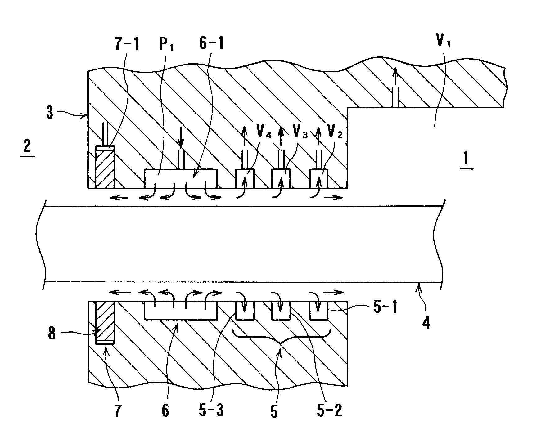
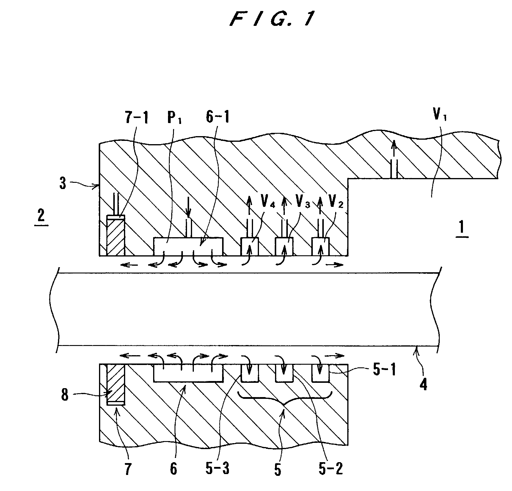
[0051]A differential pumping seal apparatus according to embodiments of the present invention will be described below with reference to the drawings. A differential pumping seal apparatus having a differential pumping seal and a hydrostatic bearing according to the present invention will be described with reference to FIGS. 1 and 2. In FIGS. 1 and 2, the differential pumping seal and the hydrostatic bearing are illustrated in a simplified manner so as to be easily understood. As shown in FIGS. 1 and 2, a partition wall 3 is disposed between a clean space region 1 serving as a first space and an atmospheric region 2 serving as a second space. A movable body 4 is provided so as to pass through the partition wall 3. An actuator (not shown) is disposed in the atmospheric region 2 and is coupled to the movable body 4. An object such as a specimen (not shown) which is disposed in the clean space region 1 can be moved by the movable body 4.
[0052]The differential pumping seal apparatus comp...
second embodiment
[0058]FIGS. 3A and 3B are views illustrating the manner in which a differential pumping seal apparatus having a differential pumping seal and a hydrostatic bearing according to the present invention is operated. FIG. 3A shows the differential pumping seal which is in operation, and FIG. 3B shows the differential pumping seal which is not in operation. In FIGS. 3A and 3B, reference numeral 8′ represents a seal member of a back up seal mechanism 7′. The seal member 8′ is made of an elastic material and has a thin lip on its tip end.
[0059]While the differential pumping seal 5 is in operation, i.e., while the working fluid discharged from the hydrostatic bearing 6 flows toward the atmospheric region 2 and the differential pumping seal 5 as indicated by the arrows in FIG. 3A, if the relationship among the pressure V1 in the clean space region 1, the pressure P0 in the atmospheric region 2, the pressure P1 in the working fluid supply port 6-1, and the pressures V2, V3 and V4 in the respec...
third embodiment
[0072]A differential pumping seal apparatus according to the present invention will be described below with reference to FIGS. 5 through 7. In this embodiment, the differential pumping seal apparatus having a differential pumping seal and a hydrostatic bearing will be described below with reference to simplified drawings.
[0073]In FIGS. 5 through 7, reference numeral 10 represents the entire structure of the differential pumping seal apparatus, and reference numeral 11 represents a first member which defines a first space 1 serving as a clean space. An outer peripheral side of the first member 11 (shown at the left side in FIG. 5) faces a second space, e.g., a second space 2 which is at atmospheric pressure. The atmosphere in the second space 2 is different from the atmosphere in the first space 1 (in terms of a pressure, cleanliness, type of a filled gas, and the like). A side wall 12 of the first member 11 has a passage 13 which passes therethrough, and the first space 1 and the se...
PUM
 Abstract
Description
Claims
Application Information