Sealing ring

a sealing ring and sealing technology, applied in the field of sealing ring, can solve the problem that the expensive vulcanization device no longer needs to be used for this purpose, and achieve the effect of reliable and secure connection

Inactive Publication Date: 2006-11-14
KACO
View PDF7 Cites 30 Cited by
  • Summary
  • Abstract
  • Description
  • Claims
  • Application Information

AI Technical Summary

Benefits of technology

[0005]It is an object of the present invention to configure a sealing ring of this kind such that it can be mounted easily and has a constructively simple configuration.
[0007]The sealing ring according to the invention is mounted without a carrying or supporting body at the mounting location. Generally, the sealing ring is fastened on the stationary machine part, for example, a housing. However, it is also possible to fasten the sealing ring on the movable machine part. Since a support or carrying body is not present, the annular disk is held directly on the machine part. The sealing ring according to the invention can be manufactured and mounted very simply and inexpensively in this way. Since a coating or a sheath must not be provided on the carrying or support body, the expensive vulcanization devices required for this purpose are no longer needed. The fastening surface on the machine part must not be machined precisely or can be left unmachined; this contributes to an inexpensive mounting of the sealing ring.
[0010]The annular disk is, in particular, a polyfluorocarbon disk, preferably, a polytetrafluorocarbon disk. It can be subjected to a plasma treatment, at least in the area with which it is fastened on the machine part, such that this fastening area has a surface roughness within the micro range. The plasma treatment as a result of plasma etching provides a sandblasting effect and / or chemical changes in the micro range of the surface. This plasma-activated range or area ensures that the annular disk can be reliably and securely connected to the machine part without this requiring the otherwise necessary etching processes by means of solutions. The plasma-treated area of the annular disk can be connected directly to the machine part, i.e., without any intermediate layer comprised of a bonding agent having to be provided. Of course, it is possible to employ such an intermediate layer, if desired.

Problems solved by technology

Since a coating or a sheath must not be provided on the carrying or support body, the expensive vulcanization devices required for this purpose are no longer needed.

Method used


Image

  • Sealing ring
  • Sealing ring
  • Sealing ring

Examples


Embodiment Construction

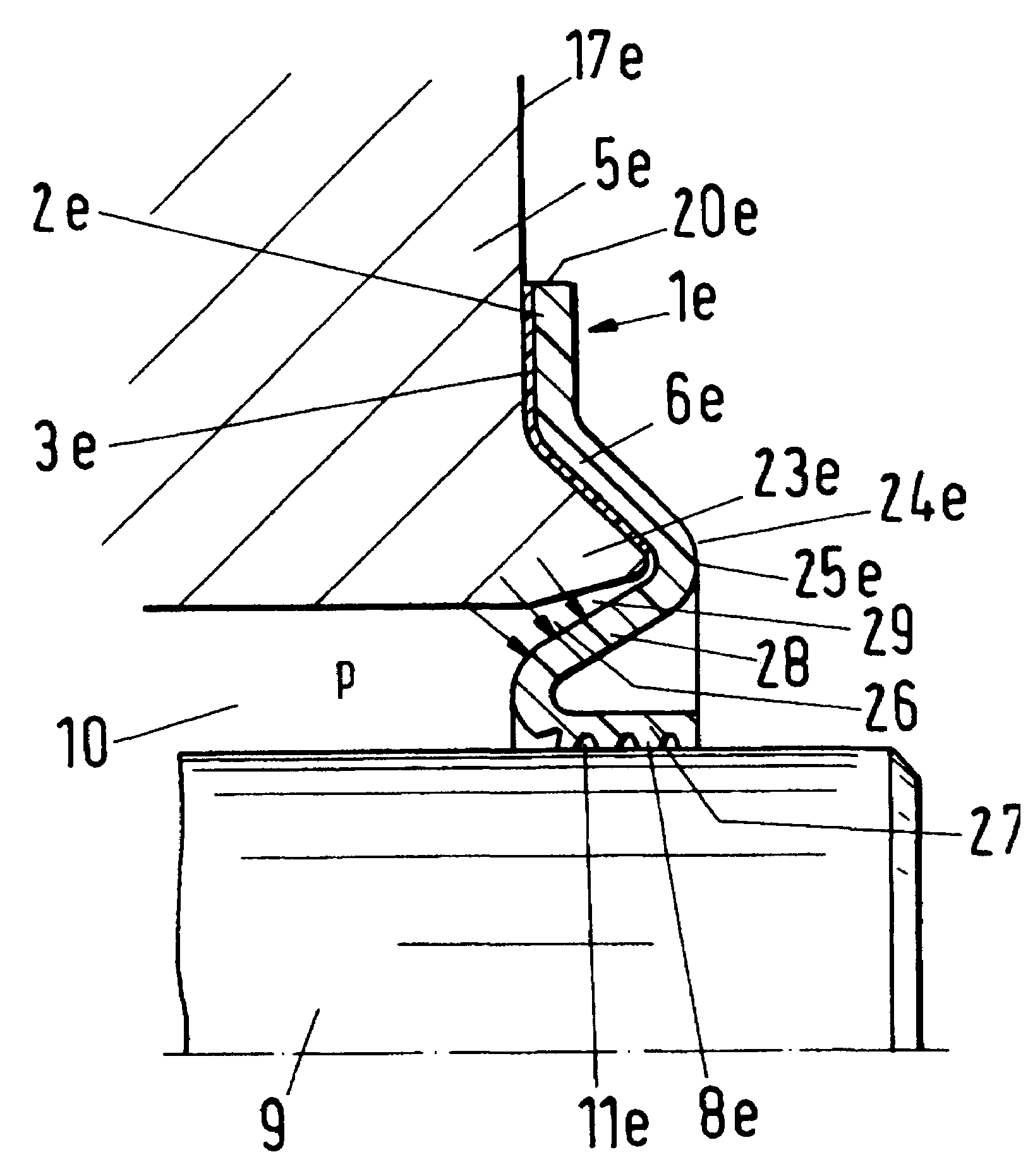
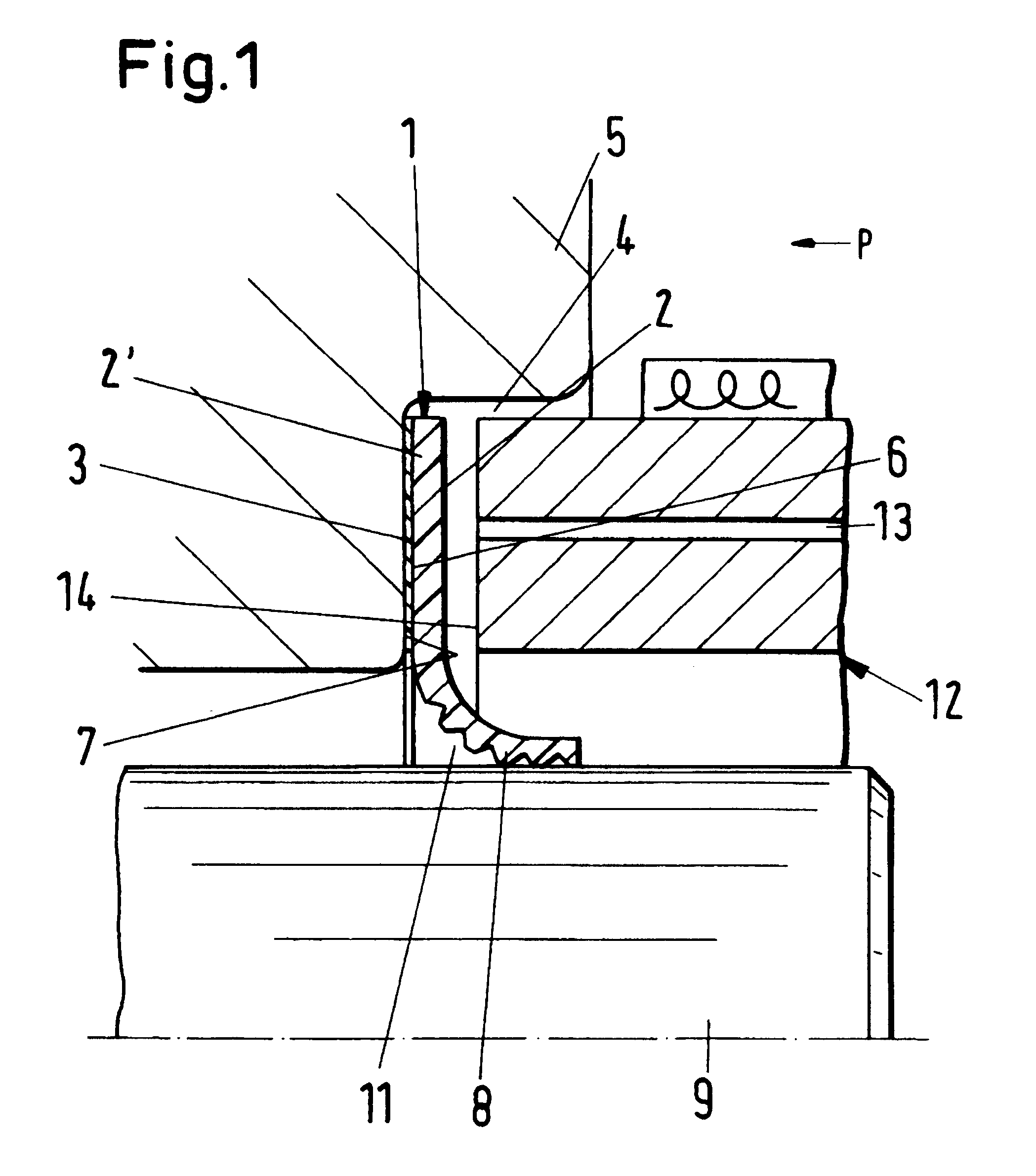
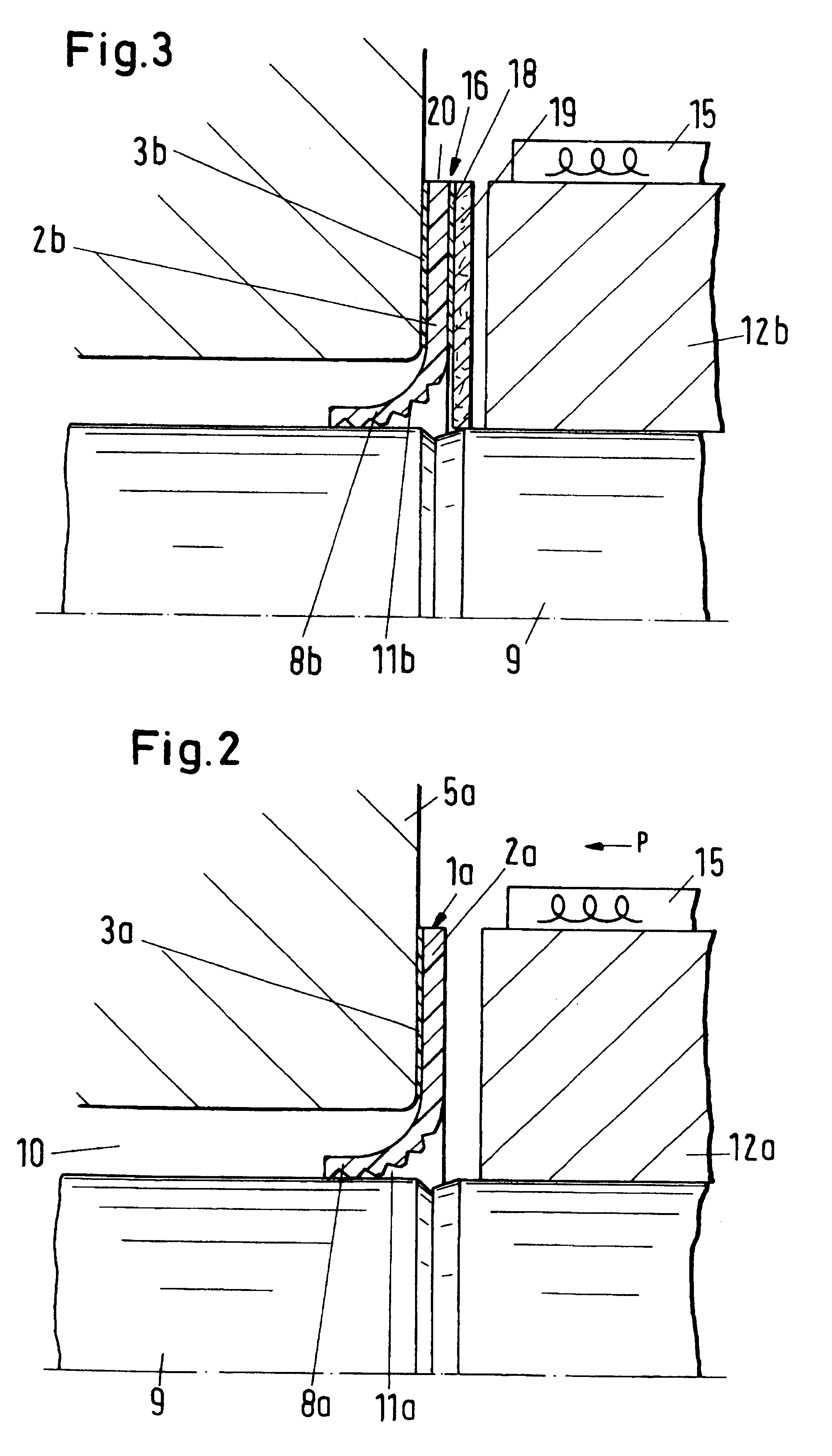
[0029]The rotary shaft seal 1 illustrated in FIGS. 1 and 12 is formed by an annular disk 2 ( FIG. 12) that has on one side 2′ an adhesive layer 3 with which it is fastened on the end face recess 4 of a machine housing 5 (not illustrated in detail). The annular disk 2 is comprised preferably of polyfluorocarbon, in particular, polytetrafluoroethylene. Of course, it can also be made of any other suitable material, for example, elastomer-modified polytetrafluoroethylene or an elastomer or a similar material. The annular disk 2 has a radial outer annular section forming a fastening part 6 for connecting the annular disk 2 to the housing 5. As illustrated in FIG. 1, the annular disk 2 is attached by means of the adhesive layer 3 directly to a bottom 7 of the recess 4.

[0030]The radial inner annular section of the annular disk 2 forms a sealing part 8 with which the annular disk 2 rests sealingly on a shaft 9 to be sealed. The shaft penetrates through a central opening 10 of the housing 5....


PUM


Abstract

A sealing ring has an annular disk with at least one fastening part secured on a first machine part and at least one sealing part that, when the sealing ring is mounted, sealingly rests against a second machine part. The annular disk is fastened without intermediate positioning of a supporting body on the first machine part. The sealing ring is a rotary shaft seal, a piston seal ring, or a rod seal. One of the first and second machine parts is stationary and the other one of first and second machine parts is moveable. A first bonding layer is attached to the annular disk, and the annular disk is connected with the first bonding layer to the first machine part. The first bonding layer is an adhesive layer.

Description

BACKGROUND OF INVENTION[0001]1. Field of the Invention[0002]The invention relates to a sealing ring, in particular, a rotary shaft seal, a piston seal ring, or a rod seal. The sealing ring comprises at least one fastening part secured on a first, preferably stationary, machine part and at least one sealing part which, when the sealing ring is mounted, sealingly rests against a second, preferably movable, machine part.[0003]2. Description of the Related Art[0004]Rotary shaft seals are known that have a cup-shaped annular body provided at least on its outer peripheral surface at least partially with a coating or sheath that is comprised of elastic material. The coating forms a static sealing part that rests in the mounted position sealingly on the wall of the mounting space. The dynamic sealing part is formed of an annular disk made of polytetrafluoroethylene that must be attached to the support body. The sealing ring is complex in its configuration and expensive in its manufacture. I...

Claims


Application Information

Patent Timeline
Patent Type & Authority Patents(United States)
IPC IPC(8): F16J15/32B25B27/00
CPCB25B27/0028F16J15/3228F16J15/3268
Inventor UHRNER, KLAUS-JURGEN
Owner KACO
Why Eureka
Try Eureka