Check patentability & draft patents in minutes with Patsnap Eureka AI!

Electron gun for cathode ray tube having SVM coil and cathode ray tube having the electron gun

a technology of electron gun and cathode ray tube, which is applied in the direction of cathode ray tube/electron beam tube, mechanical apparatus, foundation engineering, etc., can solve the problems of increasing the ability of individual electrodes to focus electron beams, deteriorating focusing characteristics caused by external electric fields, and inability to precisely control the position of electron beams, etc., to achieve the effect of maximizing the use of the magnetic field generated by the svm coil and preventing deteriorating

Inactive Publication Date: 2006-11-14
SAMSUNG SDI CO LTD
View PDF6 Cites 3 Cited by
  • Summary
  • Abstract
  • Description
  • Claims
  • Application Information

AI Technical Summary

Benefits of technology

The present invention provides an electron gun for a CRT with an SVM coil that maximizes the efficiency of using the magnetic field generated by the SVM coil and prevents deterioration in focusing characteristics caused by an external electric field. The electron gun includes a scanning velocity modulation coil mounted on the outer circumference of the neck of the CRT, a plurality of grid electrodes, a plurality of focus electrodes, supports on which the grid electrodes are fixed in a row, and a shield electrode. The shield electrode is positioned between the focus electrodes and includes a continuous space along the long axis direction of the CRT. The shield electrode includes at least one gap along a direction perpendicular to the long axis direction of the CRT. The electron gun also includes a connector for interconnecting the first and second shield electrodes. The invention provides an improved electron gun for CRTs that enhances the performance of the CRT and ensures better focusing.

Problems solved by technology

Therefore, the electron beam position is unable to be precisely controlled.
This further weakens the magnetic field acting on the electron beams.
Although a sensitivity of the magnetic field can be enhanced with increases in gap size, such increases weaken the ability of the individual electrodes to focus electron beams as a result of an electrical field that enters from an exterior of the electrodes (e.g., an electrical field formed by a connector that electrically connects the individual electrodes).
Therefore, there are limitations placed on how much the gap may be enlarged, and these limitations are such that the gap may not be made large enough to realize sufficient improvements in magnetic field sensitivity of the SVM coil.
However, the coil-shaped electrodes are mounted along all directions perpendicular to an axial direction of the CRT such that although part of the magnetic field generated by the SVM coil acts on the coil-shaped electrodes, there is no substantial increase in the effect of the SVM coil with this configuration.

Method used


Image

  • Electron gun for cathode ray tube having SVM coil and cathode ray tube having the electron gun
  • Electron gun for cathode ray tube having SVM coil and cathode ray tube having the electron gun
  • Electron gun for cathode ray tube having SVM coil and cathode ray tube having the electron gun

Examples


Embodiment Construction

[0046]Exemplary embodiments of the present invention will now be described in detail with reference to the accompanying drawings.

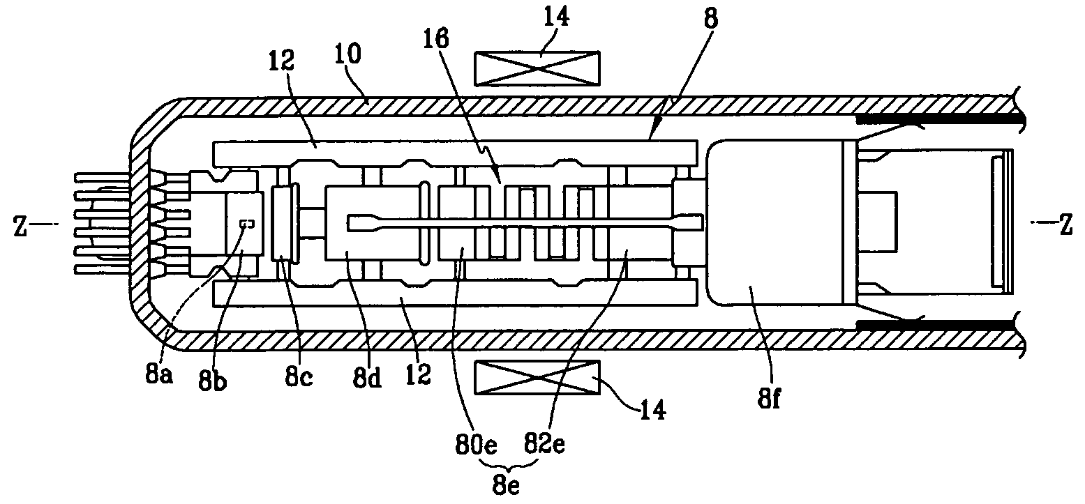
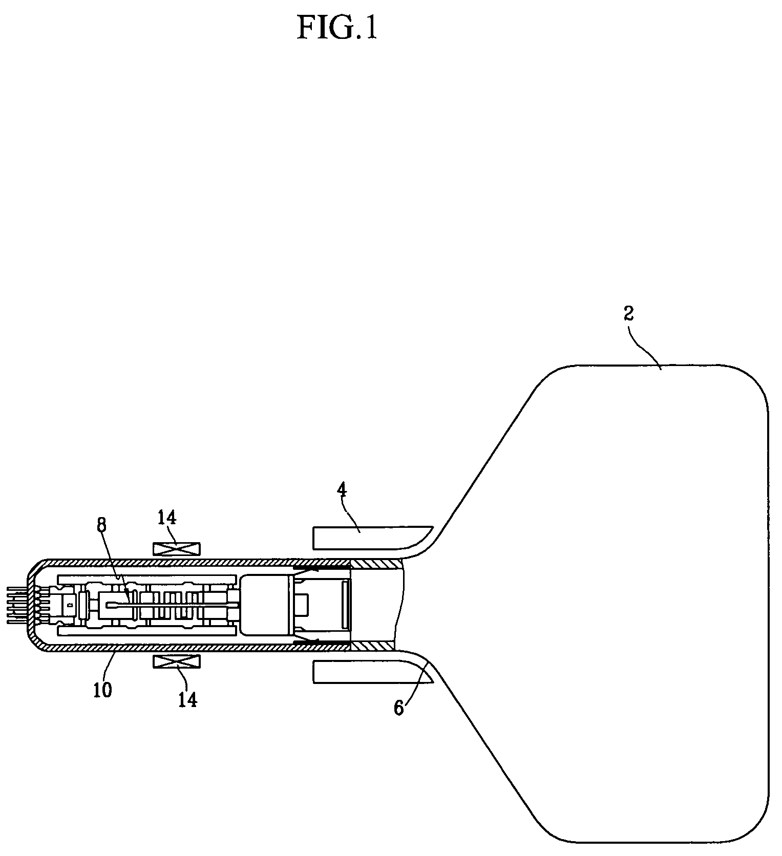
[0047]FIG. 1 is a partially cutaway sectional view of a CRT according to an embodiment of the present invention, and FIG. 2 is an enlarged partial sectional view of a neck of the CRT shown in FIG. 1.

[0048]The CRT is a projection-type CRT (or monochrome CRT) that may be applied to a display device such as a projection television. Its structure, as with the conventional CRT, includes a panel 2 on an inside surface of which is formed a phosphor screen, a funnel 6 connected to the panel 2 with a deflection device 4 mounted to an outer circumference thereof for deflecting electron beams by generating a magnetic field, and a neck 10 connected to the funnel 6 and inside of which is mounted an electron gun 8 for emitting electron beams. The panel 2, the funnel 6, and the neck 10 are fused together to form a vacuum tube assembly.

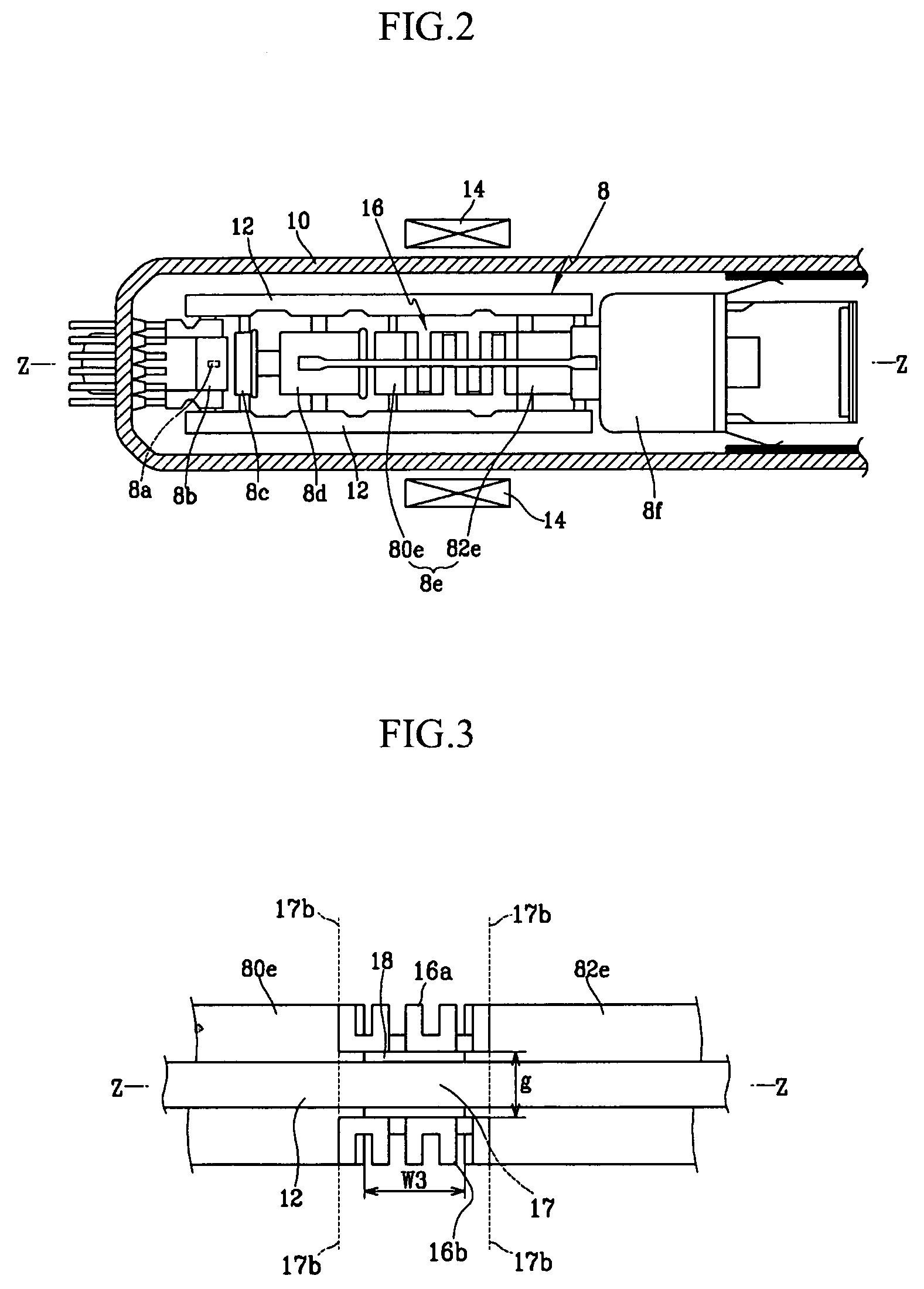
[0049]The electron gun 8 generates a...


PUM


Abstract

An electron gun for a cathode ray tube having a scanning velocity modulation coil mounted on an outer circumference of a neck of the cathode ray tube. The electron gun includes a cathode for emitting electron beams; a plurality of grid electrodes sequentially mounted starting from the cathode, and including a plurality of focus electrodes mounted with a predetermined gap therebetween; supports on which the grid electrodes are fixed in a row; and a shield electrode mounted between the focus electrodes and connected to the focus electrodes. The shield electrode defines a continuous space along an elongated axis direction of the cathode ray tube.

Description

CROSS-REFERENCE TO RELATED APPLICATION[0001]This application claims priority of Korean Patent Application number 2004-0012952, filed Feb. 26, 2004, the entire disclosure of which is incorporated herein by reference.BACKGROUND OF THE INVENTION[0002](a) Field of the Invention[0003]The present invention relates to a cathode ray tube (CRT). More particularly, the present invention relates to a CRT having a scanning velocity modulation (SVM) coil, and to an electron gun applied to this CRT.[0004](b) Description of the Related Art[0005]A CRT typically includes a panel, a funnel, and a neck, which are integrally fused to define an exterior of the CRT. A phosphor screen is formed on an interior surface of the panel. Also, an electron gun, which emits electron beams toward the phosphor screen, is mounted within the neck. The funnel is positioned between the panel and the neck, and has a deflection yoke mounted to an outer circumference thereof for deflecting the electron beams emitted from t...

Claims


Application Information

Patent Timeline
Patent Type & Authority Patents(United States)
IPC IPC(8): H01J29/46H01J29/06H01J29/48
CPCH01J29/06H01J29/484H01J29/488H01J2229/5688E03F5/021F16L5/02E02D29/12E03F2005/028
Inventor JUNG, BONG-WOOKKIM, DEOG-HOYUN, KWANG-JINHWANG, SE-JA-CHUL
Owner SAMSUNG SDI CO LTD
Features
  • R&D
  • Intellectual Property
  • Life Sciences
  • Materials
  • Tech Scout
  • Unparalleled Data Quality
  • Higher Quality Content
  • 60% Fewer Hallucinations
Learn More