Multilayered pressure vessel and method of manufacturing the same

a technology of multi-layered pressure vessels and manufacturing methods, applied in the directions of fire extinguishers, flexible container closures, transportation and packaging, etc., can solve the problems of storage and transportability inability to collapse, and achieve the effect of easy modification at manufacture and easy manufacturing

Inactive Publication Date: 2006-11-21
POUCHKAREV ALEXANDER S
View PDF6 Cites 11 Cited by
  • Summary
  • Abstract
  • Description
  • Claims
  • Application Information

AI Technical Summary

Benefits of technology

[0015]It is an object of the present invention to provide a new and improved multilayered or multi-ply pressure vessel that is readily adapted for use as a structural member.
[0016]It is another object of the present invention to provide a new and improved multilayered pressure vessel that may be readily adapted for use as a fluid container and / or fluid conveyor.
[0018]An even further object of the present invention is to provide a new and improved multilayered pressure vessel easily manufactured from a single sheet of flexible material.
[0019]A still further object of the present invention is to provide a new and improved multilayered pressure vessel easily modified at manufacture to have discrete compartments for containing, conveying, and / or segregating various materials.
[0023]Another object of the present invention is to provide a method of manufacturing a multilayered pressure vessel that is simple in concept and in execution and that obviates the need for expensive machinery.
[0026]The vessel body formed according to the inventive method summarized above may be equipped with end fittings for introducing and containing fluids in the vessel body and for connecting separate pressure vessels to one another or to other structures. Additionally, the manufacturing method facilitates the attachment of exterior and interior surface reinforcement sleeves, handles, exterior surface textures, and the like. It also facilitates the inclusion of a plurality of interior passageways. It does so because the material is ultimately turned inside-out in manufacture. Thus, in the manufacturing process, the surface that will ultimately be an interior surface in the vessel body is exposed as an exterior surface in the first steps of manufacture. Thus, until the final stages of manufacturing, there is provided a working surface for easy modification of the interior surface according to the anticipated end uses.

Problems solved by technology

Additionally, and as will be readily appreciated, the structural elements taught in each of Boxmeyer and Ross require more than pneumatic pressure to provide the desired structural characteristics, and after rigidization they are incapable of collapse for storage and transportability.

Method used


Image

  • Multilayered pressure vessel and method of manufacturing the same
  • Multilayered pressure vessel and method of manufacturing the same
  • Multilayered pressure vessel and method of manufacturing the same

Examples


embodiment 1000

[0221]FIG. 14 is an end view in elevation of a fourth preferred embodiment 1000 of a pressure vessel body 1010 in which a plurality of tuning cable sleeves 1020 are disposed on the interior surface 1030 of the outer portion 1040 of the vessel body. Affixation of the fabric pieces comprising the cable sleeves and installation of the tuning cables 1050 is accomplished in the manner described above.

[0222]FIG. 15 a cross-sectional end view in elevation of airfoil or wing 1100 having tubular pressure vessels 1110 sized and configured in a side-by-side arrangement to form and function as a wing spar assembly. As spars the pressure vessels provide support and rigidity to prevent buckling or collapse of the upper and lower airfoil surfaces 1120, 1130, respectively, of the wing, as is well known in the art.

[0223]FIG. 16 is perspective view of a pressure vessel assembly 1200 showing a plurality of tubular pressure vessels 1210 in fluid communication with one another to form an integrated mult...

embodiment 1300

[0224]FIG. 17 is a perspective view of a fifth preferred embodiment 1300 of a tubular pressure vessel 1310 having a flange 1320 attached with seams 1330 to the outer surface 1340 of the vessel. The flange includes grommets 1350 suitable for use in draping the pressure vessel from a support line 1360 (FIG. 18).

[0225]FIGS. 19 and 20 are end views in elevation showing possible configurations of connection means for adjoining tubular pressure vessels. The connection means 1400 (FIG. 19), 1500 (FIG. 20), comprises a plurality of attachments sewn or otherwise affixed to the outer surfaces 1410, 1510 of the vessel bodies and to the surfaces of any neighboring vessel body.

embodiment 1600

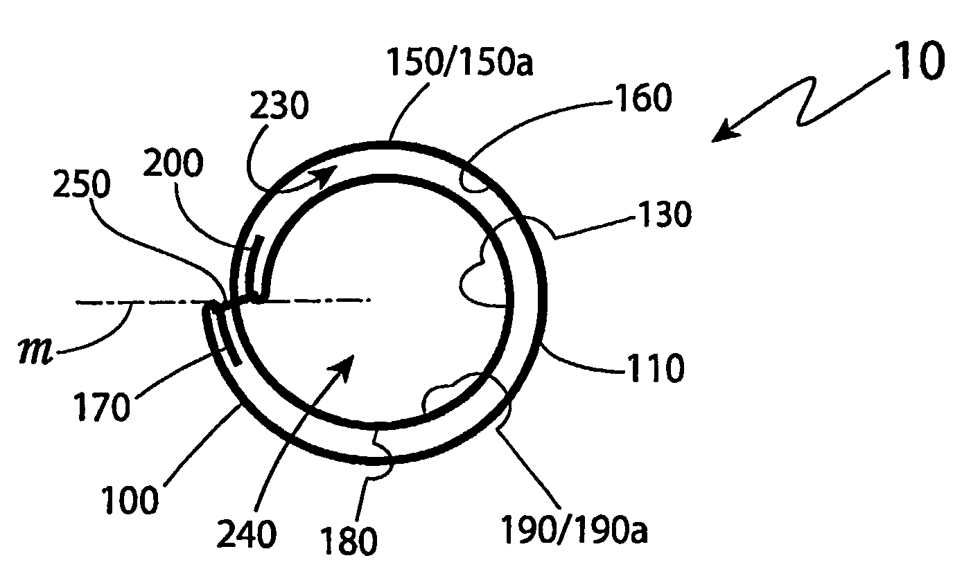
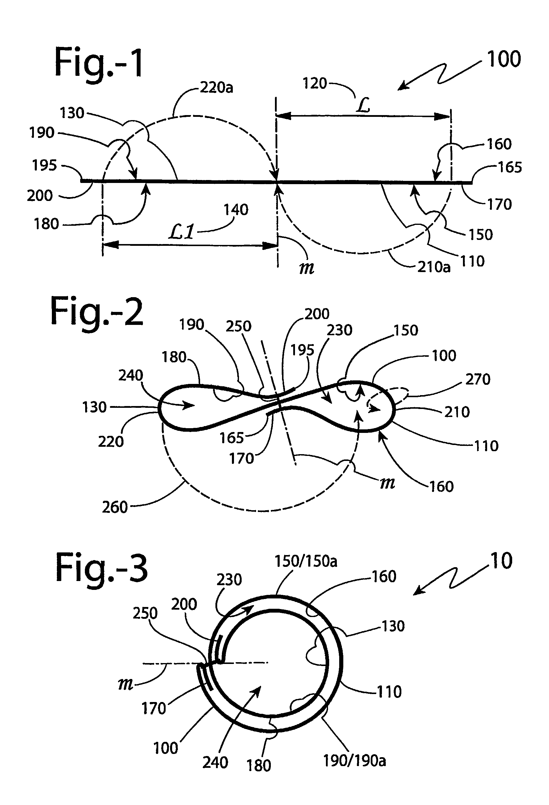
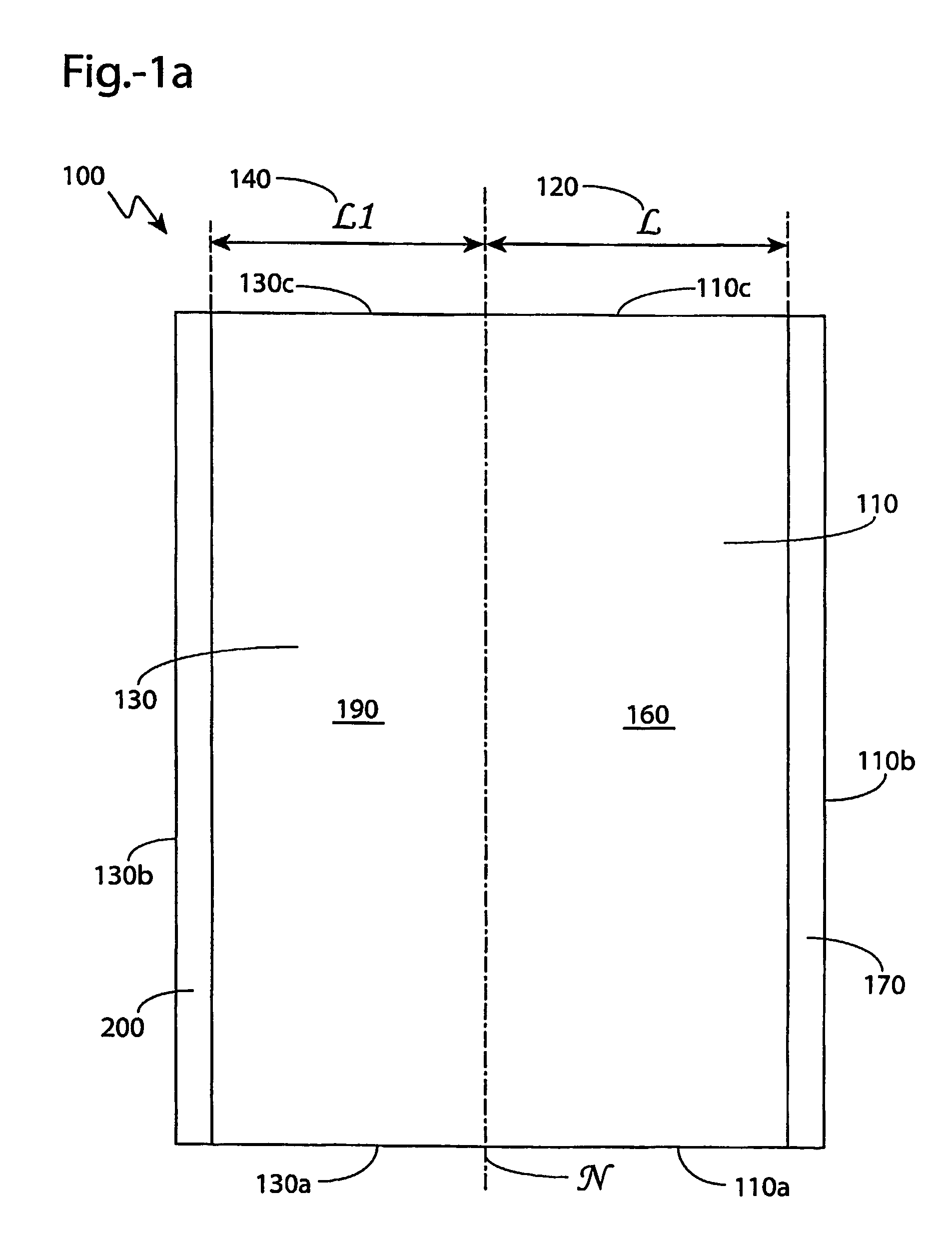
[0226]FIG. 21 is an end view showing a sixth preferred embodiment 1600 of the inventive multilayered pressure vessel. In this embodiment, two fabric sheets 1610, 1620 are initially laid out, one atop the other, each sheet having outer and inner portions with differential widths suitable for forming first through fourth fluid passageways 1630, 1640, 1650, and 1660, and having first through fourth layers 1670a–d of material forming the vessel body. As in the first preferred embodiment, the wrap forming the vessel is a continuous 720 degree wrap. When fully configured, the vessel may include one to four passageways, depending upon the dimensions of the partitioned layers and, therefore, how they separate and become spaced apart during construction. The seam 1680 spans all layers but is hidden at the surface and includes hidden segments, as earlier described.


PUM

PropertyMeasurementUnit
flexibleaaaaaaaaaa
shapeaaaaaaaaaa
pressureaaaaaaaaaa

Abstract

A multilayered pressure vessel (10) fabricated from at least one single ply sheet of flexible material (100) having an approximate longitudinal midline which divides the material into an inner portion (130) having an inner surface, an outer surface, an edge, a seam allowance, and a width, and an outer portion having an inner surface, an outer surface, an edge, a seam allowance, and a width. The width of the outer portion (120) is greater than the width of the inner portion (140). A primary seam (250) binds the outer portion and the inner portion to the material sheet at the midline proximate the outer portion edge and inner portion edge. The sheet (100) is wrapped into a continuous substantially 720 degree wrap to form a generally cylindrical vessel body having possible multiple fluid passageways, at the election of the user. The primary seam (250) is concealed.

Description

BACKGROUND OF THE INVENTION[0001]1. Technical Field[0002]The present invention relates generally both to devices for conveying or storing gasses and to structural elements such as columns, beams, struts, and the like. More particularly, the present invention relates to a light weight inflatable pneumatic structural members deployed into serviceable condition by internal gas pressure. Even more particularly, the present inventions relates to a multilayered pressure vessel suitable for use in storing and conveying gasses, and especially well-suited for use as an inflatable load-bearing element. Also disclosed is a method of manufacturing the same.[0003]2. Background Art[0004]By definition pressure vessels comprise those vessels that have an internal pressure higher than the external atmospheric pressure. Such vessels include those that contain fluids, i.e., fluid storage tanks, and those that convey fluids, such as hoses. It is known to fabricate pressure vessels of flexible rather th...

Claims


Application Information

Patent Timeline
Patent Type & Authority Patents(United States)
IPC IPC(8): F17D1/00B65D30/10B65D33/00F16J12/00F17C1/00
CPCF16J12/00F17C1/00F17C2201/0104F17C2201/0138F17C2201/0142F17C2201/0166F17C2201/0171F17C2201/0176F17C2201/018F17C2201/035F17C2201/056F17C2203/012F17C2203/0607F17C2203/0617F17C2203/0619F17C2203/0621F17C2203/0624F17C2203/0658F17C2203/066F17C2203/0663F17C2203/067F17C2203/0673F17C2203/0685F17C2205/0103F17C2205/0119F17C2205/0134F17C2205/0153F17C2205/0311F17C2205/0323F17C2205/0341F17C2205/0364F17C2205/0382F17C2209/22F17C2209/221F17C2209/227F17C2209/228F17C2209/232F17C2221/03F17C2223/0123F17C2260/011F17C2260/012F17C2270/0186F17C2270/0189F17C2270/0194F17C2270/05F17C2270/0754Y10T137/86187
Inventor POUCHKAREV, ALEXANDER S.
Owner POUCHKAREV ALEXANDER S
Why Eureka
Try Eureka