
Portable timepiece

a timepiece and portability technology, applied in the field of portability timepieces, can solve the problems of carelessly deviating bezels, deteriorating operability, and difficult rotation of bezels, and achieve the effect of not rotating carelessly, and increasing the frictional resistance of gaskets

Active Publication Date: 2006-11-21
SEIKO INSTR INC
View PDF3 Cites 27 Cited by
  • Summary
  • Abstract
  • Description
  • Claims
  • Application Information

AI Technical Summary

Benefits of technology

The present invention provides a holding mechanism for a bezel that can hold the bezel in a desired position with respect to a case band. The holding mechanism includes an annular gasket made of elastic material that makes the bezel stationary to a rotated position with respect to the case band. A holding mechanism can hold the bezel to a stationary position with respect to the case band by giving a frictional force to these. The holding mechanism also has a slip-preventing part, a lock member, and a holding ring that can hold the bezel to a stationary position by pressing the lock member to the slip-preventing part. The holding mechanism can be easily operated by the simple rotating operation of the holding ring. The holding mechanism can also be designed to prevent the bezel from being rotationally operated when the holding state is released. The holding mechanism can be designed to securely separate the lock member from the slip-preventing part when the holding state is released.

Problems solved by technology

However, as to the bezel capable of being simply rotation-operated, since its force holding a stationary state with respect to the case band is weak, it is easy that the bezel is carelessly deviated from a rotated position set by a user with effort to a position not desired by the user by an unexpected external factor and a chance.
However, reversely to this, in a case where the user rotates the bezel, the rotation of the bezel becomes difficult and thus an operability becomes deteriorated.

Method used


Image

  • Portable timepiece
  • Portable timepiece
  • Portable timepiece

Examples


first embodiment

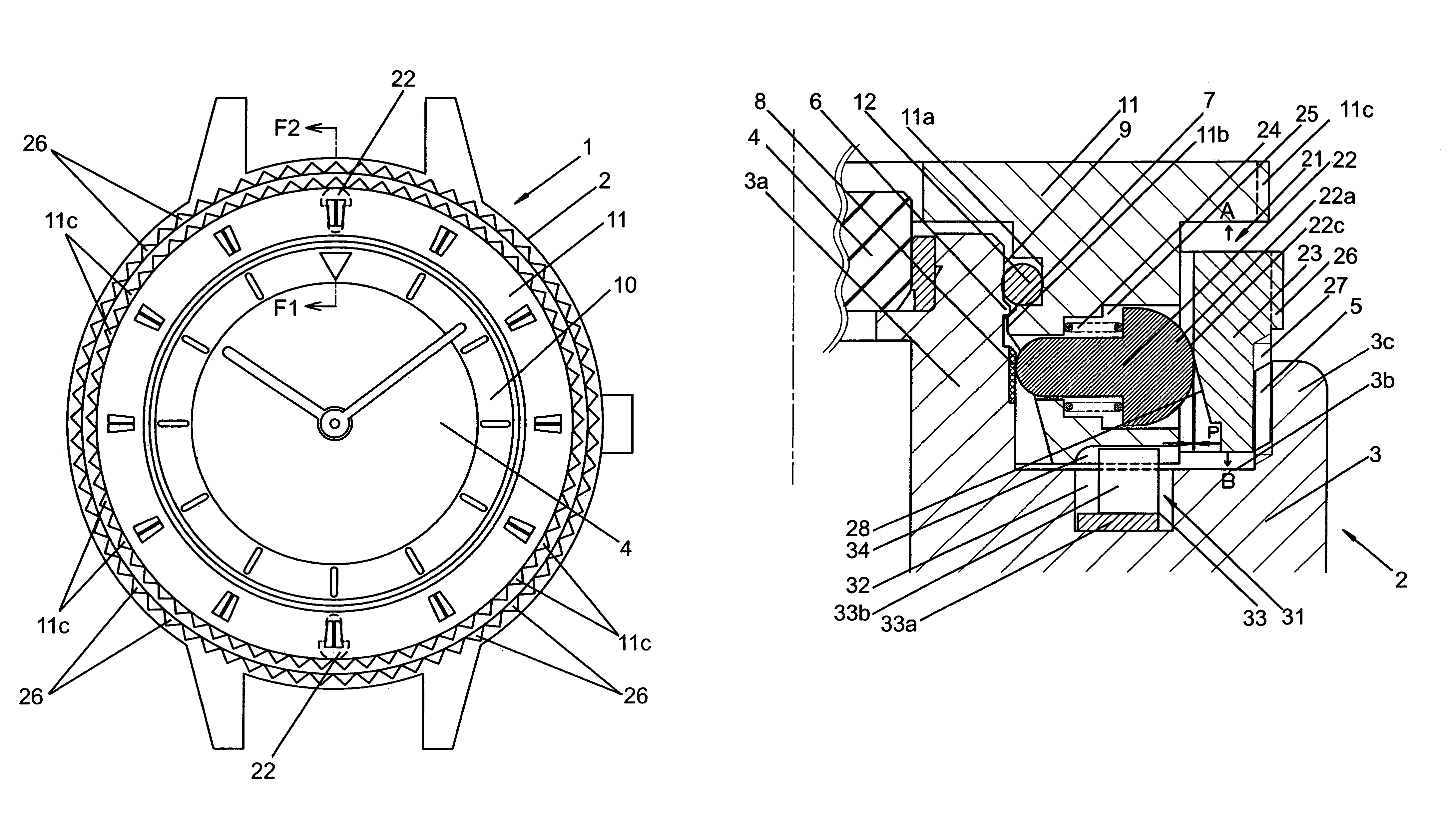
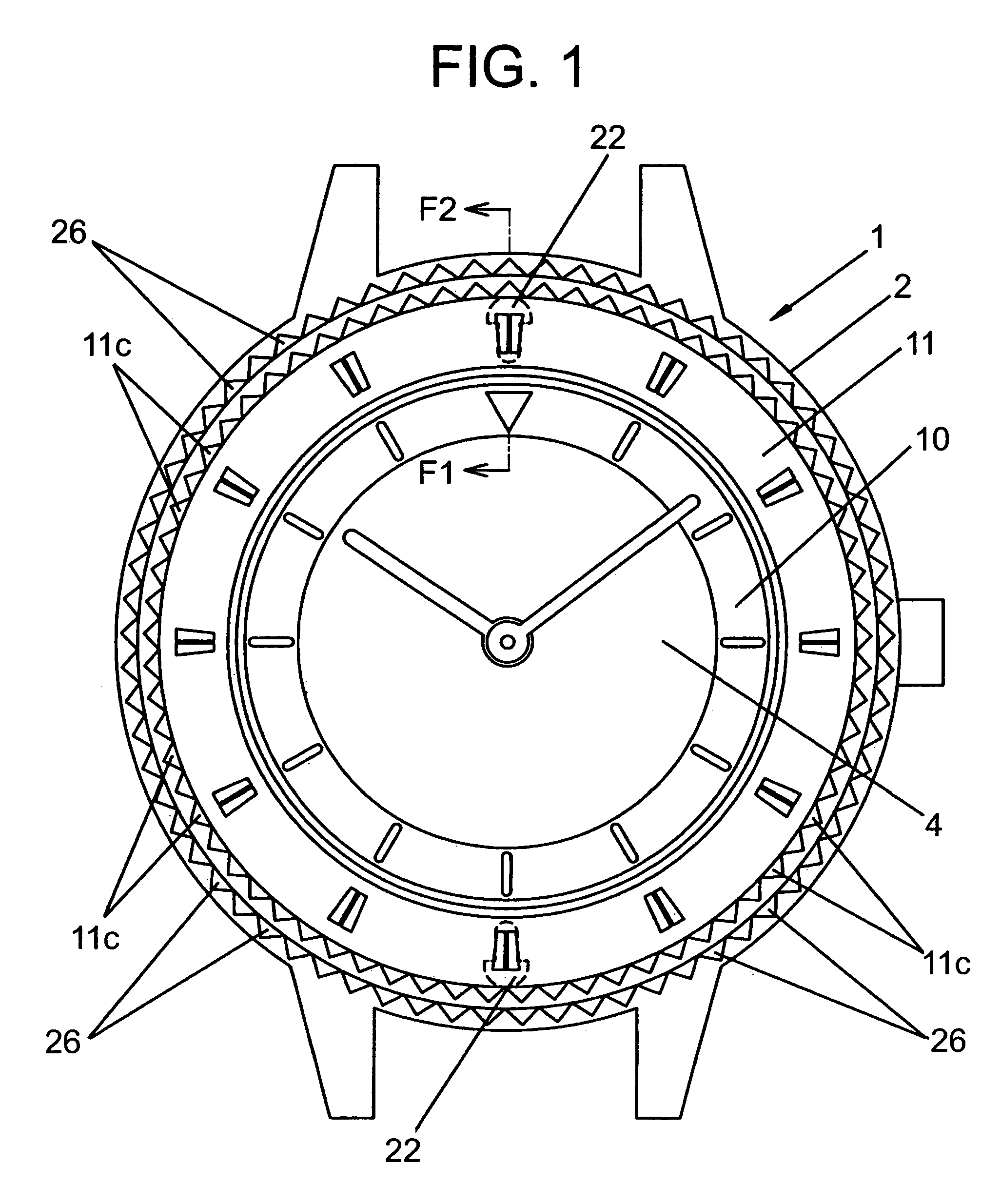
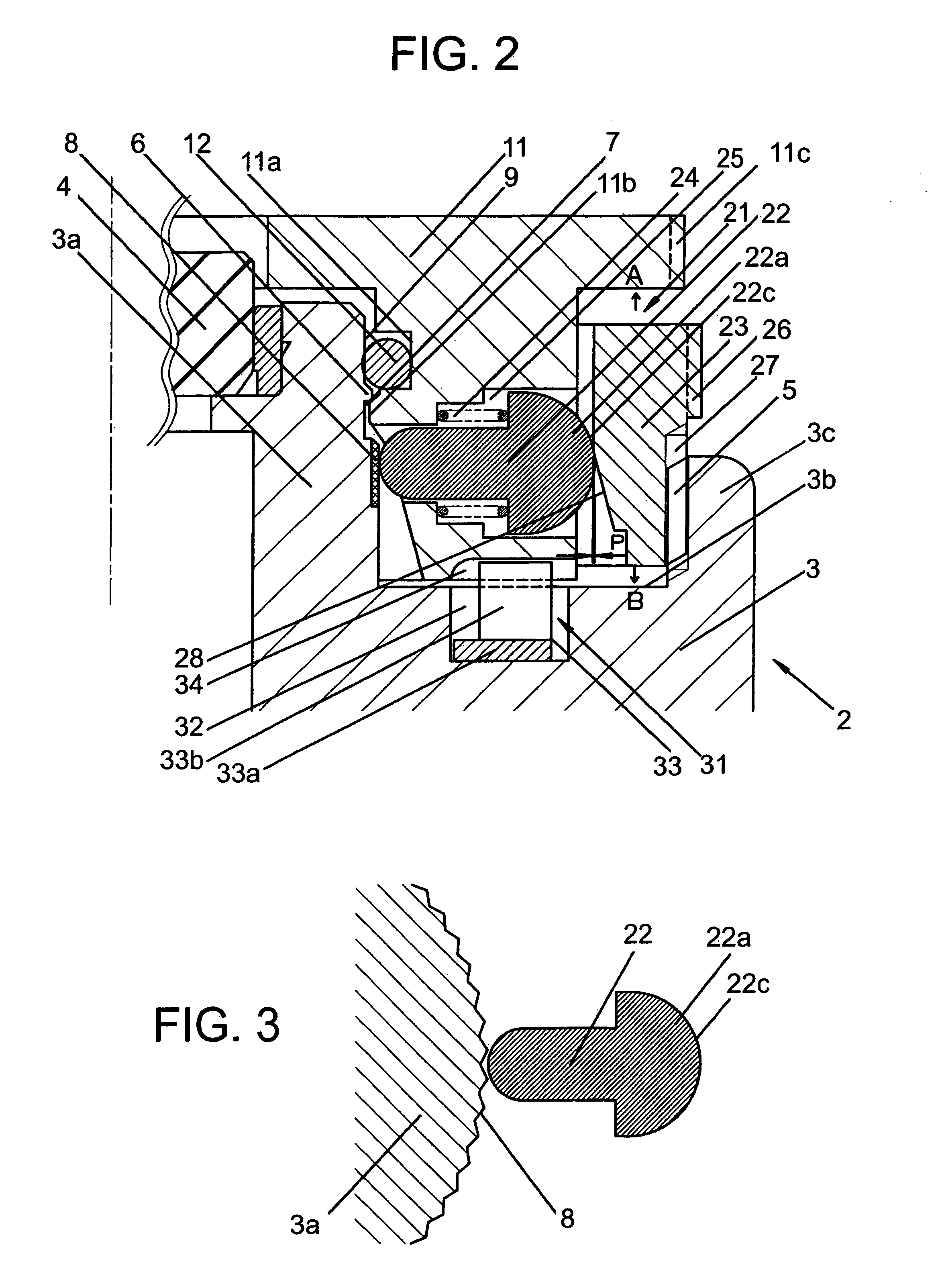
[0023]the present invention is explained with reference to FIG. 1–FIG. 3.

[0024]In FIG. 1, a reference numeral 1 denotes a portable timepiece, for example, a wristwatch used by being mounted on an arm. Inside a timepiece exterior packaging assembly 2 that the wristwatch 1 possesses, there are accommodated a dial 10, a timepiece movement not shown in the drawing, and so forth. As shown in FIG. 2, the timepiece exterior packaging assembly 2 possesses a case body in the form of a case band 3 which is annularly made of a metal or a hard synthetic resin and the like. A cover glass 4 is liquid-tightly mounted to one face (front face) in a thickness direction of the case band 3, and a case back (not shown in the drawing) is detachably mounted to the other face (back face) in the thickness direction of the case band 3. The dial 10 is visible through the cover glass 4.

[0025]As shown in FIG. 2, the case band 3 has, in its front side, an annular protrusion part 3a, an annular exterior packaging...


PUM


Abstract

A portable timepiece has a bezel rotatably disposed on a case body, and an elastically deformable gasket interposed between the case body and the bezel in an elastically deformed state to exert a frictional force on the case body and the bezel sufficient to maintain the bezel in a stationary rotational position though permitting the bezel to be manually rotated to any desired position by overcoming the frictional force. One or more lock members are movably disposed on the bezel and contact a slip-preventing part provided on the case body. A manually rotatable holding ring engages with the lock members and is rotatable in one direction to increase the contact pressure between the lock members and the slip-preventing part to thereby prevent unintended rotation of the bezel, and is rotatable in the other direction to decrease the contact pressure to thereby permit manual rotation of the bezel by overcoming the frictional force exerted by the elastically deformed gasket. In this manner, inadvertent rotation of the bezel is prevented by structure other than the gasket thereby preventing undue wear of the gasket.

Description

BACKGROUND OF THE INVENTION[0001]1. Field of the Invention[0002]The present invention concerns a portable timepiece such as wristwatch and pocket watch, and especially relates to a portable timepiece in which a bezel is rotatably attached to a case band.[0003]2. Description of the Prior Art[0004]The bezel rotatably attached to the case band of the portable timepiece can exhibit various functions by rotating it to be set to an optional position, and can contribute to increase 1n additive value of the portable timepiece.[0005]Heretofore, there is known a wristwatch in which, in order to rotatably attach the bezel to the case band, a step part, to whose inner periphery there is attached a cover glass, is formed in an upper part outer periphery of the case band over its whole periphery, an annular protrusion is formed in an outer periphery of the step part, a protrusion which is formed in an inner periphery of the bezel rotatably fitted to the step part of the case band is engaged from ...

Claims


Application Information

Patent Timeline
Patent Type & Authority Patents(United States)
IPC IPC(8): G04B37/00G04B19/28
CPCG04B19/283G04B19/286
Inventor TAKEDA, KOREMOTO
Owner SEIKO INSTR INC
Learn More