
Continuous composter

a composter and continuous technology, applied in bioreactors/fermenters, specific use bioreactors, after-treatment of biomass, etc., can solve the problems of not ensuring that all waste materials are regularly properly mixed with air, and requiring a significant amount of power to ensure its rotation, so as to achieve rapid composting and improve homogenization , the effect of easy adaptation

Active Publication Date: 2006-11-21
9087 7374 QUEBEC
View PDF11 Cites 7 Cited by
  • Summary
  • Abstract
  • Description
  • Claims
  • Application Information

AI Technical Summary

Benefits of technology

[0021]An advantage of the present invention is that the composter can continuously process waste material, in any environmental condition such as hot summer days and cold winter days.
[0022]Another advantage of the present invention is that the composter can perform rapid composting by providing process waste material with a few-hour or a few-day processing cycle.
[0023]A further advantage of the present invention is that the composter can be easily adapted depending on the type of waste material being processed and / or the required type of compost material.
[0024]Still another advantage of the present invention is that the composter ensures that substantially all of the waste material is regularly mixed with air for uniform processing and better homogenization.
[0025]Another advantage of the present invention is that the composter can be manufactured and sized according to the volume of waste material to be processed.
[0026]Yet another advantage of the present invention is that the composter has an agitator that lies substantially above the level of waste material inside the container to ensure a relatively easy rotation thereof, with as less power as possible.

Problems solved by technology

Another drawback of the prior art apparatuses is that they do not ensure that all of the waste material gets regularly properly mixed with air to better homogenize the waste material for an efficient processing, especially during a continuous processing as opposed to a batch processing.
Furthermore, in some prior apparatuses, the internal agitator dips into the waste material, thereby requiring a significant amount of power to ensure its rotation.

Method used


Image

  • Continuous composter
  • Continuous composter
  • Continuous composter

Examples


Embodiment Construction

[0062]With reference to the annexed drawings the preferred embodiments of the present invention will be herein described for indicative purpose and by no means as of limitation.

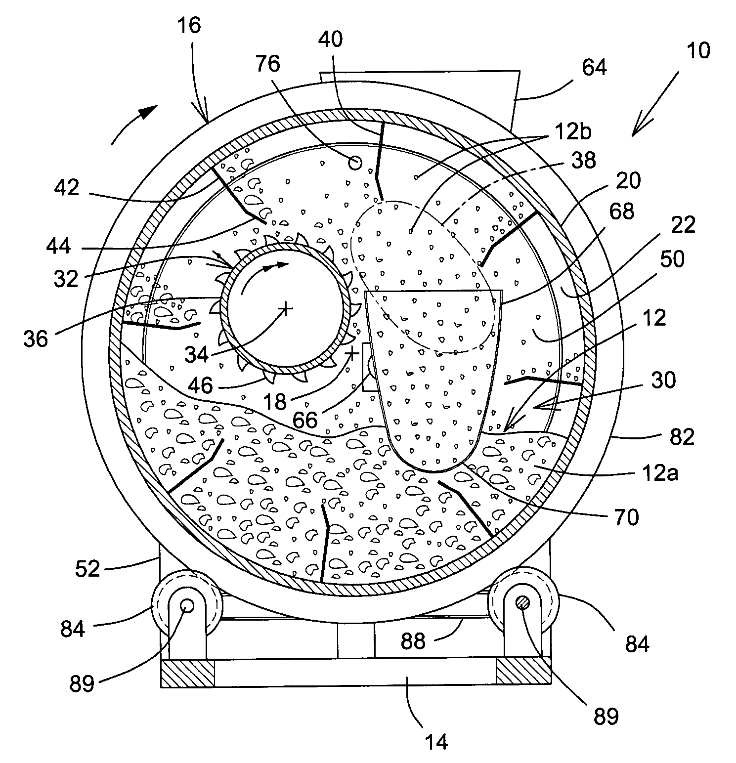
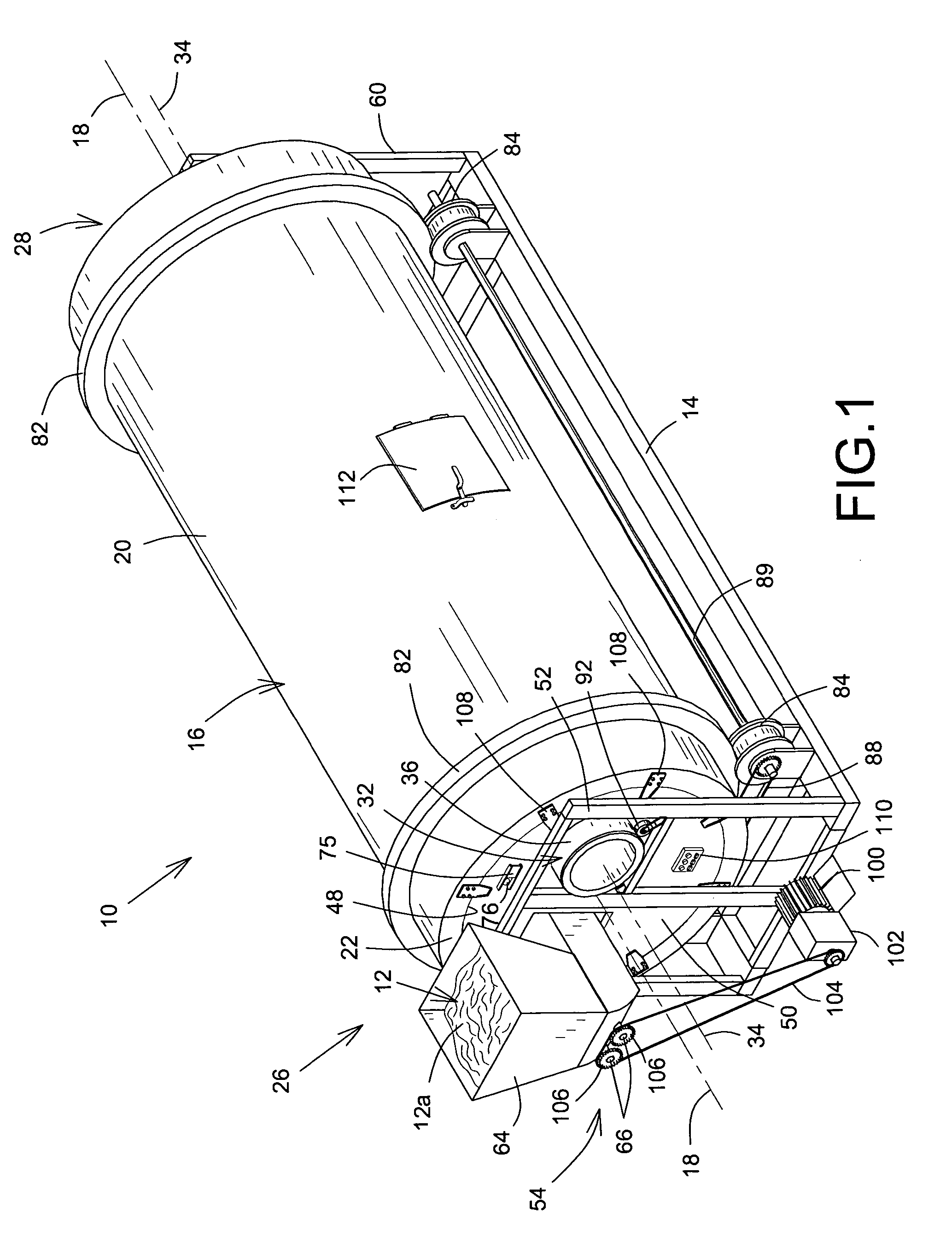
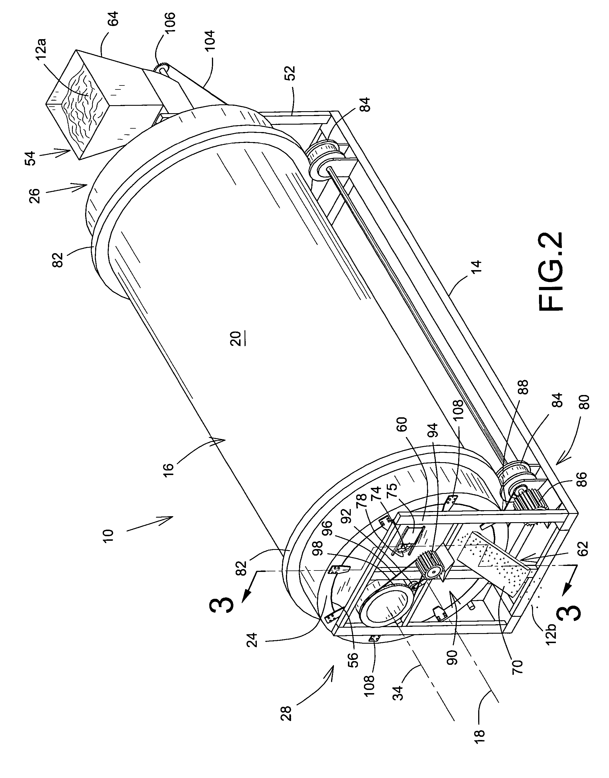
[0063]Referring to FIG. 1, there is schematically shown an embodiment of a continuous composter 10 in accordance with the present invention for continuously and biologically processing organic waste material 12 or the like that is processed from a generally heterogeneous state 12a into a generally homogenous state 12b.

[0064]As used herein, the term “heterogeneous state”12a is intended to mean at least a large proportion of either raw-like or pre-processed waste material which includes any mixture of liquid, solid and paste-like constituents which generally tend to remain as a whole and could eventually be separated in relatively large pieces.

[0065]As used herein, the term “homogenous state”12b is intended to mean a processed waste material which is a mixture of relatively small pieces that generally tend to ...


PUM


Abstract

A continuous composter for continuously processing organic waste material from a generally heterogeneous state into a generally homogenous state. The composter includes a container rotatably mounted on a support frame about its longitudinal axis that defines an inner chamber containing an amount of the heterogeneous waste material for continuous circulation therein. An agitator located within the inner chamber is rotatably mounted on fixed end walls about its own longitudinal axis that is offset relative to the container axis. The agitator is located to selectively receive the circulated waste material from the rotating container, to separate the heterogeneous waste material into the homogenous waste material, and to aerate the homogenous waste material by projecting it within the chamber. Both the container and the agitator rotates in a same direction at a relatively slow and fast rotational speed respectively.

Description

FIELD OF THE INVENTION[0001]The present invention relates to the field of composting apparatuses and methods and is more particularly concerned with an apparatus for continuous and rapid composting and its corresponding method.BACKGROUND OF THE INVENTION[0002]It is well known in the art to use elongated containers to process any type of organic waste material such as sewage sludge, animal excrements, leachate and the like into usable humus fertilizer, compost or the like material depending on the material and the specific needs.[0003]Some of these prior art apparatuses and methods are disclosed in the following documents:[0004]U.S. Pat. No. 3,676,074, issued Jul. 11, 1972, to Daigoro Shibayama et al. for “Apparatus for treating organic waste”;[0005]U.S. Pat. No. 3,837,810, issued Sep. 24, 1974, to Richards et al. for “Composter”;[0006]U.S. Pat. No. 3,845,939, issued Nov. 5, 1974, to Waldenville for “Composting apparatus”;[0007]U.S. Pat. No. 4,072,494, issued Feb. 7, 1978, to Gujer f...

Claims


Application Information

Patent Timeline
IPC IPC(8): C12M1/02C05F17/02
CPCC05F17/0223C05F17/929Y02W30/40Y02P20/145
Inventor PRATTE, JEAN-PIERRE
Owner 9087 7374 QUEBEC
Learn More