Unlock instant, AI-driven research and patent intelligence for your innovation.

Device and method for inspection

Inactive Publication Date: 2006-11-21
OHT
View PDF3 Cites 10 Cited by
  • Summary
  • Abstract
  • Description
  • Claims
  • Application Information

AI Technical Summary

Benefits of technology

[0008]It is therefore an object of the present invention to provide an inspection apparatus and inspection method capable of eliminating the need for any pin to be brought into contact with a circuit wiring when supplying an inspection signal to the circuit wiring and capable of detecting any invisible microscopic defects.

Problems solved by technology

However, recent progressive densification in the conductive pattern makes it difficult to assure a sufficient space for bringing the pins into contact with the circuit wiring accurately and simultaneously.
This means that such techniques are unavailable if a circuit wiring is so fine as to preclude the pin from bringing into contact therewith.
Further, extremely fine conductive objects such as fragments of a conductive pattern attached on a circuit board as dusts during manufacturing processes of the circuit board or the like cannot be practically inspected by such techniques because such objects cannot be visually distinguished.

Method used


Image

  • Device and method for inspection
  • Device and method for inspection
  • Device and method for inspection

Examples


Embodiment Construction

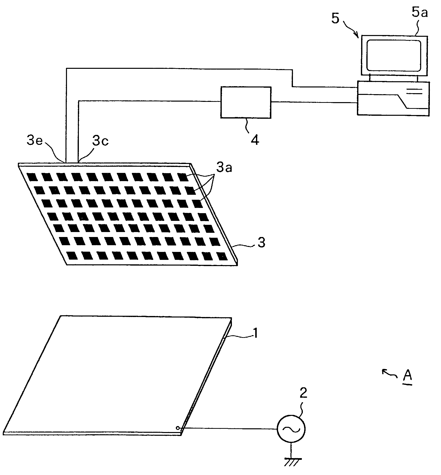
[0033]FIG. 1 is a schematic block diagram showing an inspection apparatus A according to one embodiment of the present invention. FIG. 2 illustrates the state when a circuit board 100 is inspected by the inspection apparatus A (which is partially cut-away and drawn in perspective).

[0034]

[0035]The inspection apparatus A comprises a conductive member 1 adapted to be supplied with an inspection signal, a signal source 2 for supplying the inspection signal to the conductive member 1, a sensor unit 3 having a plurality of cells 3a, a signal-processing unit 4 for processing signals (hereafter referred to as “output signal”) appearing at the cells 3a, and a computer 5 for controlling the sensor unit 3 and acquiring the processed output signal from the signal-processing unit 4.

[0036]As shown in FIG. 2, the conductive member 1 is disposed on the side of one of the surfaces (the bottom surface in FIG. 2) of the circuit board 100 during inspection. In this embodiment, the conductive member 1 i...


PUM


Abstract

The present invention provides an inspection apparatus and an inspection method, capable of, when supplying an inspection signal to a circuit wiring, eliminating any need for a pin to be brought into contact with the circuit wiring and detecting any defects including an invisible microscopic defect. An inspection apparatus A for inspecting a circuit wiring of a circuit board 100 comprises a conductive member 1 adapted to be disposed on the side of one of surfaces of the circuit board 100 and to be supplied with an inspection signal, a signal source 2 for supplying the inspection signal to the conductive member 1, a sensor unit 3 including a plurality of cells 3a to be disposed the opposed to the conductive member 1 on the side of the other surface of the circuit board 100, and a computer 5 for acquiring each signal appearing at the cells 3a in response to the inspection signal supplied to the conductive member 1.

Description

TECHNICAL FIELD[0001]The present invention relates to inspection of a circuit wiring of a circuit board.BACKGROUND ART[0002]In manufacturing processes of a circuit board, after forming a circuit wiring (electrically conductive pattern) on a board, it is required to inspect the presence of defects, such as disconnection or short-circuit, in the circuit wiring.[0003]As for such an inspection technique, a contact type inspection technique has heretofore been known in which a circuit wiring was subjected to a continuity check or the like by bringing two separate pins into contact with the opposed ends of the circuit wiring to apply an inspection signal (electric signal) from one of the two pins to the circuit wiring ant then receive the inspection signal through the other pin.[0004]However, recent progressive densification in the conductive pattern makes it difficult to assure a sufficient space for bringing the pins into contact with the circuit wiring accurately and simultaneously. Th...

Claims


Application Information

Patent Timeline
IPC IPC(8): G01R27/26G01R31/08G01R31/02G01N27/24G01R31/28G01R31/304G01R31/312H01L21/66H05K3/00
CPCG01R31/2805G01R31/2812G01R31/304G01R31/312H01L2924/0002H01L22/12H01L2924/00
Inventor ISHIOKA, SHOGOYAMAOKA, SHUJI
Owner OHT