Transmission type laminated hologram optical element and image display device comprising this optical element

a technology of optical elements and laminated holograms, which is applied in the field of transmission-type laminated hologram optical elements and image display devices comprising this optical element, can solve the problems of low light utilization efficiency, inability to optimally set the distance between the color filter and the color pixels of the spatial light modulation element, and the diffraction efficiency of incident polarized ligh

Inactive Publication Date: 2006-11-21
SONY CORP
View PDF12 Cites 73 Cited by
  • Summary
  • Abstract
  • Description
  • Claims
  • Application Information

AI Technical Summary

Benefits of technology

[0024]An object of the present invention is to provide a novel transmission type laminated hologram optical element and a novel image display apparatus using such an optical element which can solve the problems that conventional image display apparatuses have.
[0025]Another object of the present invention is to provide a transmission type laminated hologram optical element in which diffraction acceptance angle of incident light is widened so that light utilization efficiency is caused to be high to have the ability to optimally set the distance with respect to the color pixels of spatial light modulation element from viewpoints of manufacturing difficulty and / or light utilization efficiency.
[0026]A further object of the present invention is to provide an image display device and an image display apparatus in which a transmission type laminated hologram element which can attain the above-described objects is used to thereby have the ability to display a bright image.

Problems solved by technology

As a result, dependency of diffraction efficiency by incident polarized light appears.
In the transmission type hologram as described above, since diffraction acceptance angle of incident light is narrow, and the diffraction acceptance angle and the outgoing angle are not sufficiently separated, light utilization efficiency is low.
As a result, it is impossible to optimally set the distance between the color filter and color pixels of spatial light modulation element from viewpoints of manufacturing difficulty and / or light utilization efficiency.
Namely, in this image display apparatus, it is impossible to realize improvement in light utilization efficiency by a broad angle of view and / or a broad-band of illumination light with respect to the color filter.
As a result, a bright image cannot be obtained.

Method used


Image

  • Transmission type laminated hologram optical element and image display device comprising this optical element
  • Transmission type laminated hologram optical element and image display device comprising this optical element
  • Transmission type laminated hologram optical element and image display device comprising this optical element

Examples


second embodiment

[0090]Now, explanation will be given with reference to FIG. 13 in connection with the image display device of the reflection type according to the present invention using the previously described holographic PDLC (polarization selective hologram optical element). As shown in FIG. 13, a transmission type laminated hologram optical element 36 in this embodiment is of the laminated structure of two layers of a hologram layer 34 for blue light provided between glass bases (substrates) 81, 82, and a hologram layer 35 for green light provided between glass bases (substrates) 82, 83, and is constituted integrally with a reflection type liquid crystal element 37 for blue and green.

[0091]This image display device serves to allow blue light (A) and green light (B) to be incident at incident angles different from each other. The blue light hologram layer 34 and the green light hologram layer 35 have diffraction acceptance angles different from each other.

[0092]Blue light diffracted at the blue...

third embodiment

[0096]Now, the image display device according to the present invention will be explained with reference to FIG. 14.

[0097]As shown in FIG. 14, a second blue light diffraction hologram layer 40 and a second green light diffraction hologram layer 41 having incident angle acceptance ranges different with respect to respective blue light hologram layer 34 and green light hologram layer 35 and outgoing angles corresponding thereto which are different from each other are supplemented (added) to thereby broaden the acceptance range of incident angle as indicated by rays of illumination light (A) to (A)′ and (B) to (B)′ to have ability to improve light utilization efficiency.

fourth embodiment

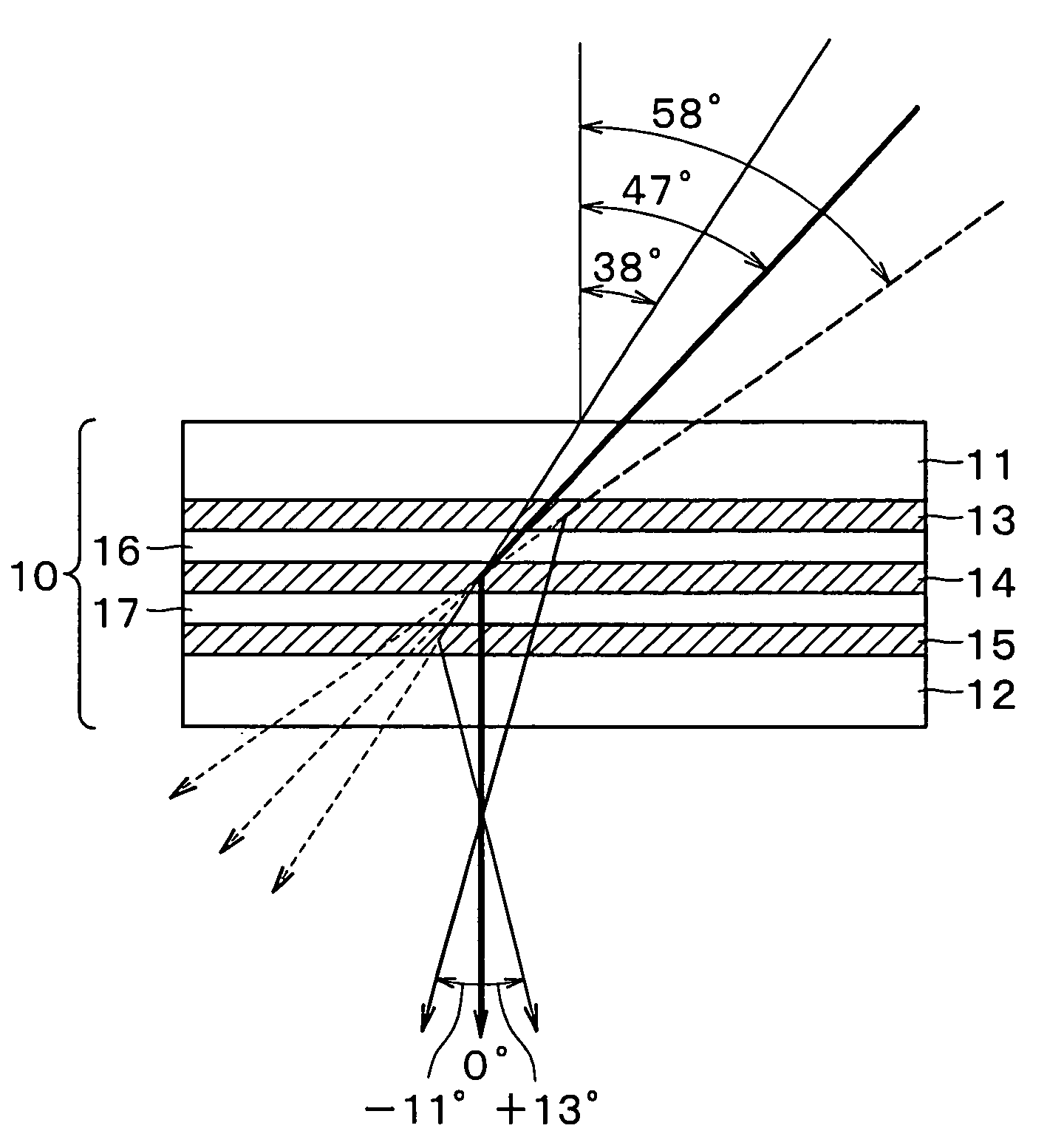
[0098]the image display device according to the present invention is shown in FIG. 15. The image display device shown in FIG. 15 is caused to be of the configuration for separating white illumination light into three colors of red light, green light and blue light and converging them by holographic PDLC (polarization selective hologram optical element) as shown in FIG. 15. Similarly to the previously described holographic PDLC of two color separation, this holographic PDLC is laminated through barrier layers 16, 17 between hologram layers 33, 35, 42 of three layers for green light diffraction, blue light diffraction and red light diffraction in which diffraction acceptance angles and outgoing angles corresponding thereto are different from each other. This image display device is caused to be of the configuration in which the holographic PDLC is optically closely in contact with the reflection type perpendicular orientation liquid crystal element 18 through glass base (substrate) 19...


PUM

PropertyMeasurementUnit
incident anglesaaaaaaaaaa
incident angleaaaaaaaaaa

Abstract

The present invention is directed to a transmission type laminated hologram optical element constituting an image display apparatus, wherein plural transmission type hologram optical elements (13), (14), (15) where diffraction acceptance incident angles are different from each other are laminated. The respective transmission type hologram optical elements are adapted so that outgoing angles with respect to center incident angles of respective diffraction acceptance incident angles at an arbitrary wavelength of the visible region are different from each other, whereby a diffraction acceptance angle of incident light can be broadened, light utilization efficiency is permitted to be high, and distance with respect to color pixels of the spatial light modulation element can be optimally set from viewpoints of light utilization efficiency.

Description

TECHNICAL FIELD[0001]The present invention relates to a transmission type laminated hologram optical element of wide angle of view, and further relates to an image display device and an image display apparatus using such transmission type laminated hologram optical element.[0002]This Application claims priority of Japanese Patent Application No. 2001-335404, filed on Oct. 31, 2001, the entirety of which is incorporated by reference herein.BACKGROUND ART[0003]As a projection type image display apparatus using a reflection type spatial light modulation element, e.g., reflection type TN liquid crystal panel, an image display apparatus constituted as shown in FIG. 1 is conventionally proposed. In this image display apparatus, light beams emitted from a lamp light source 107 are incident on an illumination optical system 108 having functions such as correction of light beam cross sectional shape, uniformization of intensity and divergence angle control, etc. This illumination optical sys...

Claims


Application Information

Patent Timeline
Patent Type & Authority Patents(United States)
IPC IPC(8): G02B5/32G03H1/26G02B27/28G02F1/1335G02F1/13357
CPCG02B5/32G02F1/133504G03H1/02G03H1/0252G02F2001/133521G03H2001/0413G03H2001/267G03H2250/41G03H2260/12G03H2260/33G02F1/133521G03H1/22
Inventor MUKAWA, HIROSHI
Owner SONY CORP
Why Eureka
Try Eureka