
Cluster-based defect detection testing for disk drives

a cluster-based, disk drive technology, applied in the field of disk drives, can solve the problems of not taking into account random nature of the present disk defect testing technique, and not taking into account the reoccurrence of cluster regions across many different disks for statistical quality control purposes

Active Publication Date: 2006-11-21
WESTERN DIGITAL TECH INC
View PDF21 Cites 100 Cited by
  • Summary
  • Abstract
  • Description
  • Claims
  • Application Information

AI Technical Summary

Benefits of technology

[0016]In one embodiment, the microprocessor under the control of the cluster detection program may count a total number of both data defect clusters and servo defect clusters that have been identified and a defect cluster record of both identified data defect clusters and servo defect clusters may be generated. This defect cluster record may be transmitted to a defect database.
[0017]In one embodiment, the microprocessor under the control of the cluster detection program for each identified data defect cluster and servo defect cluster may associate a cluster number and a corresponding head. Further, for each identified data defect cluster and servo defect cluster, a total number of defects may be calculated as well as a cluster density. Furthermore, for identified data defect clusters, other attributes may be determined such as a centroid track, a centroid wedge, as well as cluster shape.
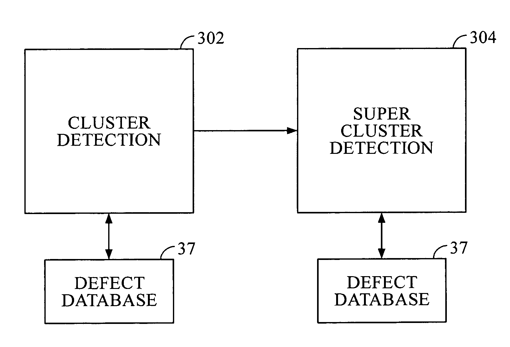
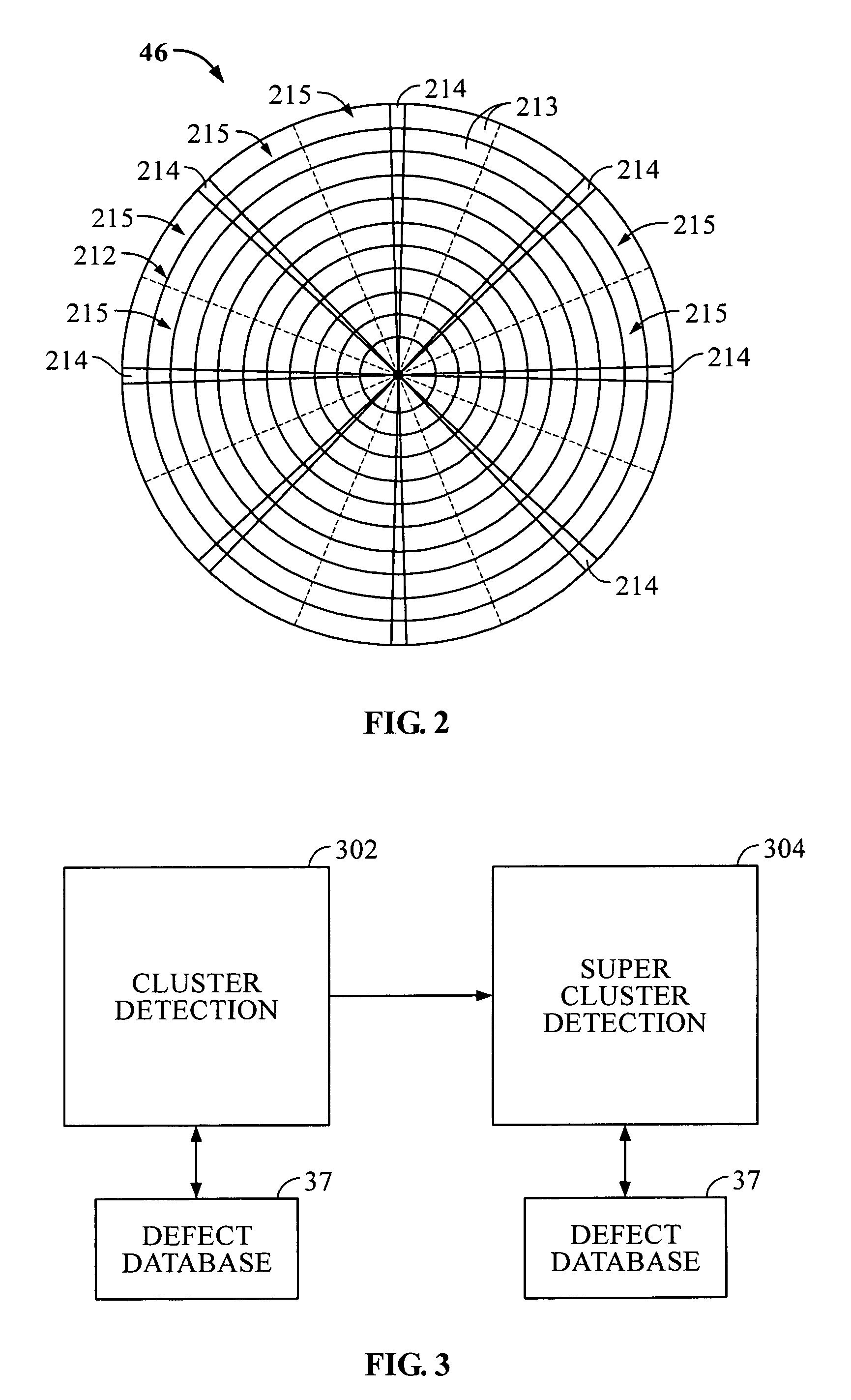
[0018]In one embodiment, the microprocessor under the control of the cluster detection program may further define a radial super cluster window based on a number of tracks and wedges and a radial super cluster event threshold based on a minimum number of centroids for corresponding identified data defect clusters required to occur within the radial super cluster window. If the minimum number of centroids for the corresponding identified data defect clusters are determined to be in the radial super cluster window, then a super radial data defect cluster may be identified. Additionally, the microprocessor under the control of the cluster detection program may further define a circumferential super cluster window based on a number of tracks and a circumferential super cluster event threshold based on a minimum number of centroids for corresponding data defect clusters that are required to occur within the circumferential super cluster window. If the minimum number of centroids for the corresponding identified data defect clusters are determined to be in the circumferential super cluster window, then a super circumferential data defect cluster is identified.
[0019]In one embodiment, the microprocessor under the control of the cluster detection program generates a super cluster event record of both identified super circumferential data defect clusters and super radial defect clusters. This super cluster event record may be transmitted to a defect database.

Problems solved by technology

These defects may also be caused by head loading, head slap, and delamination.
Unfortunately, these techniques do not take into account the random nature that characterizes the way that defects often occur on disk and the irregular shapes formed by these randomly occurring defects.
Moreover, present disk defect testing techniques do not take into account the reoccurrence of cluster regions across many different disks for statistical quality control purposes.
For example, the reoccurrence of particular cluster defect regions at specific areas across many different disks may indicate a problem with the assembly process or with disks being provided by a disk vendor for assembly into the disk drive.

Method used


Image

  • Cluster-based defect detection testing for disk drives
  • Cluster-based defect detection testing for disk drives
  • Cluster-based defect detection testing for disk drives

Examples


Embodiment Construction

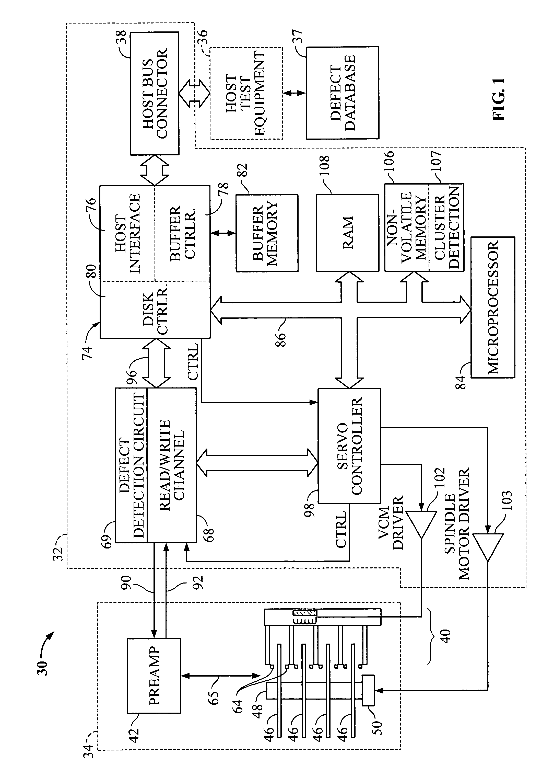
[0035]FIG. 1 shows a block diagram of a disk drive, such as a hard disk drive 30, in which embodiments of the invention may be practiced, connected to host test equipment 36 and defect database 37. One suitable standard for such connection is the Advance Technology Attachment (ATA) standard presently favored for desktop personal computers. Disk drive 30 comprises a Head / Disk Assembly (HDA) 34 and a controller printed circuit board assembly, PCBA 32.

[0036]The HDA 34 comprises: one or more disks 46 for data storage; a spindle motor 50 for rapidly spinning each disk 46 (four shown) on a spindle 48; and an actuator assembly 40 for moving a plurality of heads 64 in unison over each disk 46. The heads 64 are connected to a preamplifier 42 via a cable assembly 65 for reading and writing data on disks 46. Preamplifier 42 is connected to channel circuitry in controller PCBA 32 via read data line 92 and write data line 90.

[0037]Controller PCBA 32 comprises a read / write channel 68, servo contr...


PUM

PropertyMeasurementUnit
areaaaaaaaaaaa
defect detectionaaaaaaaaaa
thresholdaaaaaaaaaa

Abstract

Disclosed are techniques related to cluster-based defect detection testing for disk drives. A disk drive comprises a disk, a moveable head to scan the tracks of the disk, and a defect detection circuit to detect defects on the disk scanned by the moveable head. The disk drive includes a microprocessor for controlling operations in the disk drive including cluster-based defect detection. The microprocessor under the control of a cluster detection program defines a scan window. The scan window corresponds to an area of the disk scanned by the moveable head. The microprocessor under the control of the cluster detection program further defines a cluster threshold corresponding to a minimum number of defects required to occur within the scan window and identifies a defect cluster if a cluster threshold of defects occurs within the scan window. By identifying defect clusters on the disk these defect clusters can be margined.

Description

BACKGROUND OF THE INVENTION[0001]1. Field of the Invention[0002]The present invention relates to disk drives. More particularly, the present invention relates to techniques for cluster-based defect detection testing for disk drives.[0003]2. Description of the Prior Art and Related Information[0004]Today, computers are routinely used both at work and in the home. Computers advantageously enable file sharing, the creation of electronic documents, the use of application specific software, and electronic commerce through Internet and other computer networks. Typically, each computer has a storage peripheral such as a disk drive (e.g. a hard disk drive).[0005]Hard disk drives often employ a moveable head actuator to frequently access large amounts of data stored on the disk. A conventional hard disk drive has a head disk assembly (“HDA”) including at least one magnetic disk (“disk”), a spindle motor for rapidly rotating the disk, and a head stack assembly (“HSA”) that includes a head gim...

Claims


Application Information

Patent Timeline
Patent Type & Authority Patents(United States)
IPC IPC(8): G11B5/02
CPCG11B20/18G11B20/1816
Inventor ARCHIBALD, NEVIN A.IQBAL, TARIQVIGLIONE, JOSEPH M.
Owner WESTERN DIGITAL TECH INC
Learn More