Method and system for removing artifacts in compressed images

Active Publication Date: 2006-11-21
MONUMENT PEAK VENTURES LLC
View PDF10 Cites 20 Cited by
  • Summary
  • Abstract
  • Description
  • Claims
  • Application Information

AI Technical Summary

Benefits of technology

[0010]The present invention provides improved blocking and ringing artifact removal without overly smoothing desirable image content. The degree o

Problems solved by technology

It is well known that an image that has been compressed using the DCT can produce objectionable artifacts at high compression levels, which corresponds to high levels of quantization.
A common problem for all of these techniques is providing an adequate reduction in the artifacts while still preserving desirable image content.
While this method provides a significant reduction in the appearance of artifacts, particularly at high compression levels, it still suffers from several disadvantages.
First, the type of processing that is applied to the boundary regions can result in a blu

Method used


Image

  • Method and system for removing artifacts in compressed images
  • Method and system for removing artifacts in compressed images
  • Method and system for removing artifacts in compressed images

Examples


Example

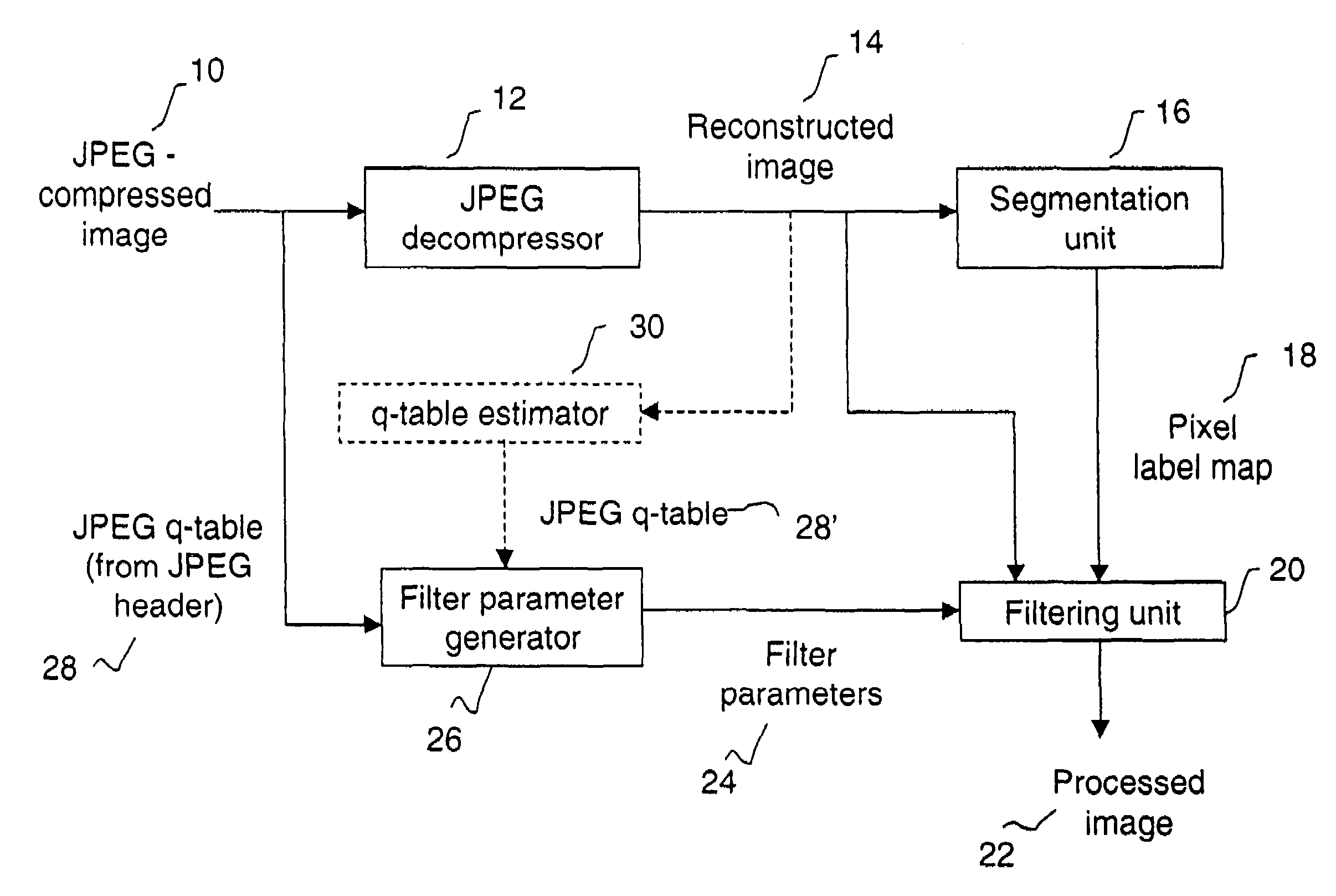
[0018]In the following description, a preferred embodiment of the present invention will be described in terms that would ordinarily be implemented as a software program. Those skilled in the art will readily recognize that the equivalent of such software may also be constructed in hardware. Because image manipulation algorithms and systems are well known, the present description will be directed in particular to algorithms and systems forming part of, or cooperating more directly with, the system and method in accordance with the present invention. Other aspects of such algorithms and systems, and hardware and / or software for producing and otherwise processing the image signals involved therewith, not specifically shown or described herein, may be selected from such systems, algorithms, components and elements known in the art. Given the system as described according to the invention in the following materials, software not specifically shown, suggested or described herein that is ...


PUM


Abstract

In a method for removing artifacts in a digital image that has been decoded from a compressed representation of the image, the pixels of the digital image are segmented into low detail pixels, high detail pixels, and boundary pixels, and then a single non-linear filtering method, such as a sigma filtering method, is applied to each pixel in the digital image. By selecting separate filter parameters for the low detail, high detail, and boundary pixels, the removal of artifacts is improved over prior methods.

Description

FIELD OF THE INVENTION[0001]The invention relates generally to the field of digital image processing, and in particular to removing artifacts from compressed images.BACKGROUND OF THE INVENTION[0002]The JPEG (Joint Photographic Experts Group) and MPEG (Moving Picture Experts Group) standards for image compression have been adopted for many diverse digital imaging applications. A commonality between these standards is the use of the discrete cosine transform (DCT). In both JPEG and MPEG, the pixel values that represent an original image are divided into non-overlapping, contiguous 8×8 blocks. Each 8×8 block is then transformed with the DCT to produce 64 spatial frequency coefficients. The lowest frequency coefficient is termed the DC coefficient, and it is related to the mean of the original 8×8 block of pixel values. The other 63 coefficients are termed the AC coefficients, and they represent the fluctuations of the pixel values around the mean. The 8×8 DCT that is used in JPEG and M...

Claims


Application Information

Patent Timeline
IPC IPC(8): G06K9/40G06K9/34G06K9/36H04B14/04G06T5/00G06T5/20G06T9/00H04N1/409H04N1/41H04N7/26
CPCG06T5/20G06T5/002H04N19/117G06T7/10H04N19/182H04N19/44H04N19/527H04N19/85H04N19/14G06T2207/20012G06T2207/20192
Inventor JONES, PAUL W.JACOBY, KEITH A.
Owner MONUMENT PEAK VENTURES LLC
Why Eureka
Try Eureka