
Mobile communication terminal

Active Publication Date: 2006-11-21
MAXELL HLDG LTD
View PDF24 Cites 9 Cited by
  • Summary
  • Abstract
  • Description
  • Claims
  • Application Information

AI Technical Summary

Benefits of technology

[0010]Embodiments of the present invention are directed to a mobile communication device such as a mobile terminal or a mobile phone that includes a plurality of antennas for receiving signals and is configured to reduce the deterioration of the antennas characteristics. In specific embodiments the mobile device is a folding type mobile communication terminal having the structure that permits easy opening or closing and enabling stabilization of the antenna characteristic.
[0012]In some embodiments, the signal processing circuit comprises a CDMA signal processing circuit. The signals received by the plurality of antennas are connected through the coupling portion to a radio circuit. The coupling portion includes a pair of lands and is configured such that the signal received by a first antenna of the plurality of antennas is transmitted directly to the radio circuit and the signal received by a second antenna of the plurality of antennas is transmitted to the radio circuit through the pair of lands so as to weaken a degree of coupling between the signal received by the first antenna and the radio circuit at the pair of lands.

Problems solved by technology

However, the related art does not reveal anything about a constituent feature suitable for a mobile communication terminal shaped to be able to be folded.
However, because the linear antenna and the surface mounting antenna are adjacently disposed, upon storing the linear antenna as contracted into the casing, its top portion and casing portion to cover the surface mounting antenna might be wrapped by a user's hand, suffering from the deterioration of the antennas characteristics as required.

Method used


Image

  • Mobile communication terminal
  • Mobile communication terminal
  • Mobile communication terminal

Examples


first embodiment

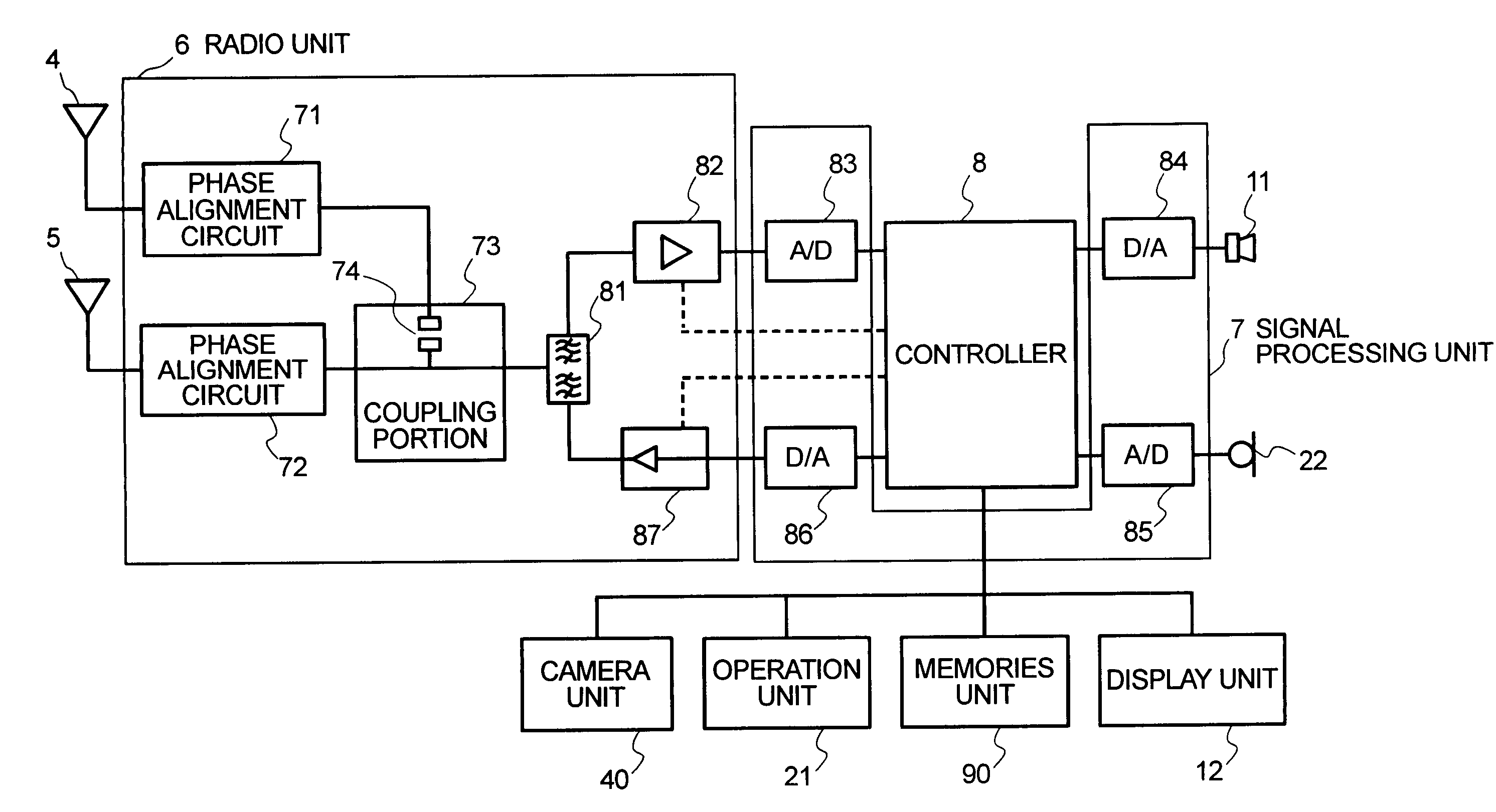
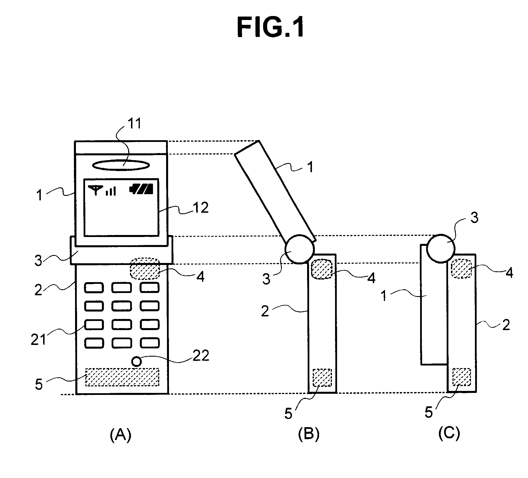
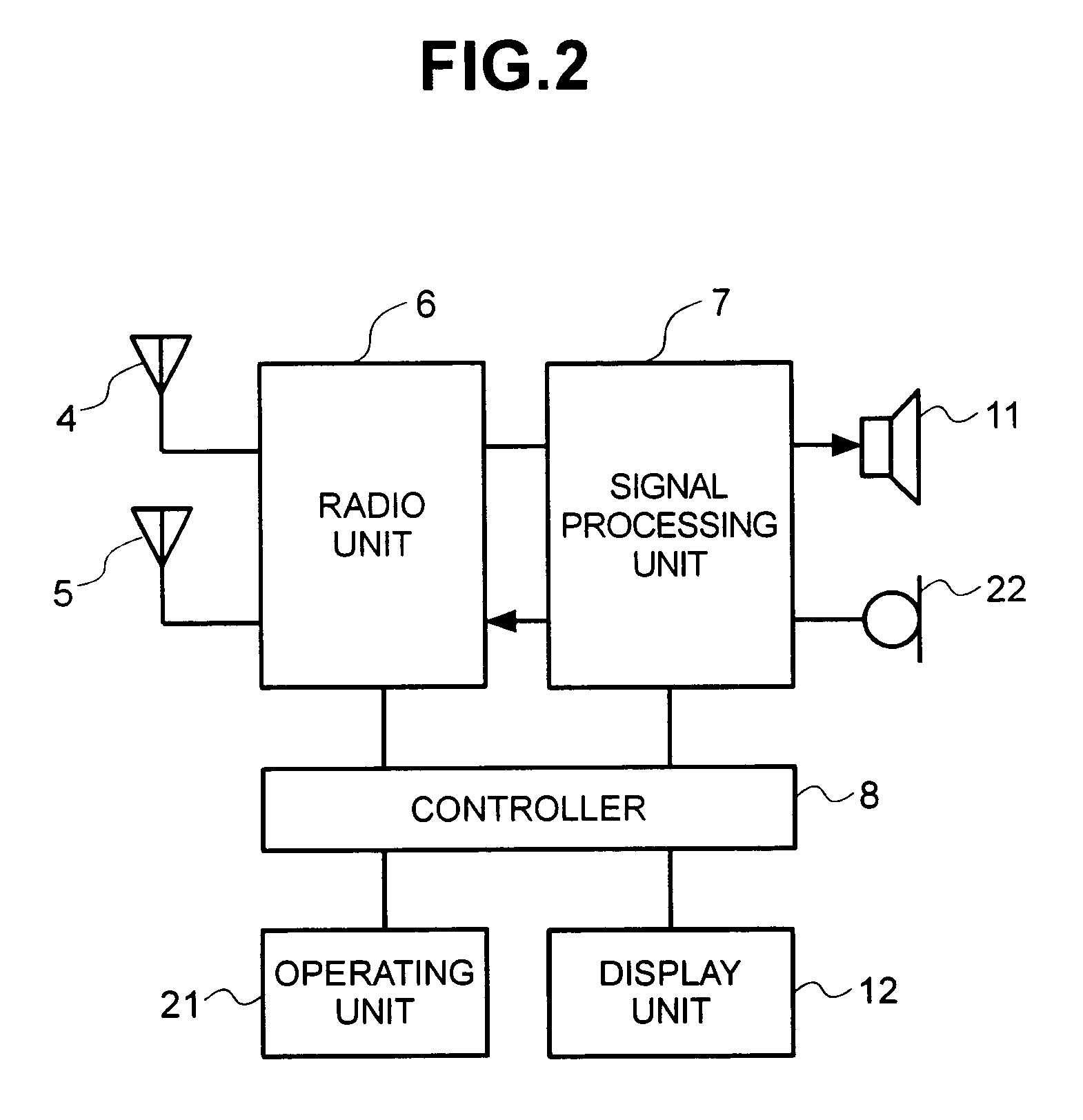
[0027]FIG. 1 shows the construction of a mobile communication terminal in accordance with the present invention. The terminal includes a first housing 1 and a second housing 2. The housings are joined by a hinge 3 so that they can pivot on the hinge. The first housing 1 includes an ear receiver 11 that transmits an audio signal and a display unit 12 on which a communicating situation or the contents of communication are displayed. The second housing 2 includes an operating unit 21 used to enter information that is received by the terminal, and a microphone 22 through which an audio signal is received.

[0028]To begin with, the positional relationship between the housings will be described. FIG. 1(A) is a front view of the terminal that is to be operated. FIG. 1(B) is a side view of the terminal, and FIG. 1(C) is a side view of the terminal being folded. As apparent from FIG. 1(C), the end surfaces of the housings included in the present embodiment are nearly parallel to the axis of ro...

fourth embodiment

[0033]FIG. 5 shows the construction of a mobile communication terminal in accordance with the present invention. According to the foregoing embodiments, the antennas are provided in one of the housings. According to the present embodiment, the antennas are included in the respective housings. As shown in FIG. 5, the antenna 4 is provided in the first housing 1 having the display unit 12, while the antenna 5 is provided in the second housing 2. Since the antennas are thus included in the respective housings, especially when a user operates the terminal while looking at the screen, the positions of the antennas are separated from each other. This suppresses interaction between the antennas and improves the antenna characteristic.

[0034]In particular, when the antennas are, as shown in FIG. 5(B), located near the end surfaces of the housings on the sides of the housings opposite to the sides thereof adjoining the hinge 3, as long as the mobile communication terminal is opened for use, t...


PUM


Abstract

Embodiments of the present invention are directed to a mobile communication device that includes a plurality of antennas for receiving signals and is configured to reduce the deterioration of the antennas characteristics. In specific embodiments the mobile device is a folding type mobile communication terminal having the structure that permits easy opening or closing and enabling stabilization of the antenna characteristic. In one embodiment, a mobile communication device comprises a plurality of antennas configured to receive signals; a signal processing circuit configured to combine and process the signals received from the plurality of antennas; and a phase alignment circuit provided for each of the plurality of antennas and configured to subject a phase of a signal received by each of the plurality of antennas to an in-phase adjustment.

Description

CROSS-REFERENCES TO RELATED APPLICATIONS[0001]This application relates to and claims priority from Japanese Patent Application No. 2002-277046, filed on Sep. 24, 2002 and Japanese patent Application No. 2002-316980, filed on Oct. 31, 2002, the entire disclosures of which are incorporated herein by reference.BACKGROUND OF THE INVENTION[0002]1. Technical Field of the Invention[0003]The present invention relates to a mobile communication terminal having a plurality of antennas, such as a cellular phone or a personal digital assistant (PDA).[0004]2. Related Art[0005]Proposals have been made of a technology for stabilizing the antenna characteristic such as antenna gain or radiation efficiency irrespective of whether a terminal is held in a hand, put into a pocket, or the like (see, e.g., Japanese Unexamined Patent Application Publication No. 11-274966). The above publication describes the use of an embedded antenna in addition to a rod-like antenna in order to stabilize the antenna char...

Claims


Application Information

Patent Timeline
IPC IPC(8): H04B1/02H04B7/02H01Q1/24H04B1/40H01Q3/30H01Q21/28H04B1/38
CPCH01Q1/243H01Q1/244H01Q3/30H01Q21/28H04B1/3838H04B1/40
Inventor KATAGISHI, MAKOTOTAKAKI, TAKUCHIBA, YUTAKAKUMEKAWA, MASANOBUHOSHINO, KAZUNORI
Owner MAXELL HLDG LTD
Features
  • Generate Ideas
  • Intellectual Property
  • Life Sciences
  • Materials
  • Tech Scout
  • Unparalleled Data Quality
  • Higher Quality Content
  • 60% Fewer Hallucinations
Learn More