System and method for rejecting far-field signals using an implantable cardiac stimulation device

a far-field signal and implantable technology, applied in the direction of internal electrodes, transvascular endocardial electrodes, therapy, etc., can solve the problems of difficult to reliably detect only p-waves, misinterpreted p-wave signals generated in the ventricles,

Inactive Publication Date: 2006-11-21
PACESETTER INC
View PDF6 Cites 37 Cited by
  • Summary
  • Abstract
  • Description
  • Claims
  • Application Information

AI Technical Summary

Benefits of technology

[0020]FIG. 10 is a block diagram illustrating components of a second exemplary embodiment of the improved atrial sense amplifier of FIG. 5, which employs a XOR-gate.

Problems solved by technology

A long-standing problem with atrial sensing is that electrical signals generated in the ventricles often appear within the atrial signals and can be misinterpreted as P-waves.
Even when sensed with leads mounted within the atria, the far-field R-waves often appear with at least the same magnitude as the near-field P-waves, making it quite difficult to reliably detect only P-waves.
Accordingly, detection circuitry designed to detect events within the atrial signal may have trouble distinguishing between the P-waves and R-waves and, in particular, may count both events as P-waves for the purposes of atrial rate calculation, likely resulting in the calculated atrial rate being twice the actual atrial rate.
For ICDs configured to deliver a high energy cardioversion shock to terminate atrial fibrillation, the erroneous calculation of the atrial rate may result in a painful cardioversion shock being delivered even though none is actually required.
When using the circuit of FIG. 2 to process atrial signals, such as those shown in FIG. 1, both the near-field P-wave and the far-field R-wave trigger a sense pulse due to their significant voltage swings, resulting in erroneous detection of the atrial rate, erroneous overdrive rate adjustments, and possible delivery of an unnecessary cardioversion shock.

Method used


Image

  • System and method for rejecting far-field signals using an implantable cardiac stimulation device
  • System and method for rejecting far-field signals using an implantable cardiac stimulation device
  • System and method for rejecting far-field signals using an implantable cardiac stimulation device

Examples


Embodiment Construction

[0021]The following description includes the best mode presently contemplated for practicing the invention. The description is not to be taken in a limiting sense but is made merely for the purpose of describing the general principles of the invention. The scope of the invention should be ascertained with reference to the issued claims. In the description of the invention that follows, like numerals or reference designators will be used to refer to like parts or elements throughout.

[0022]Overview of Implantable Device

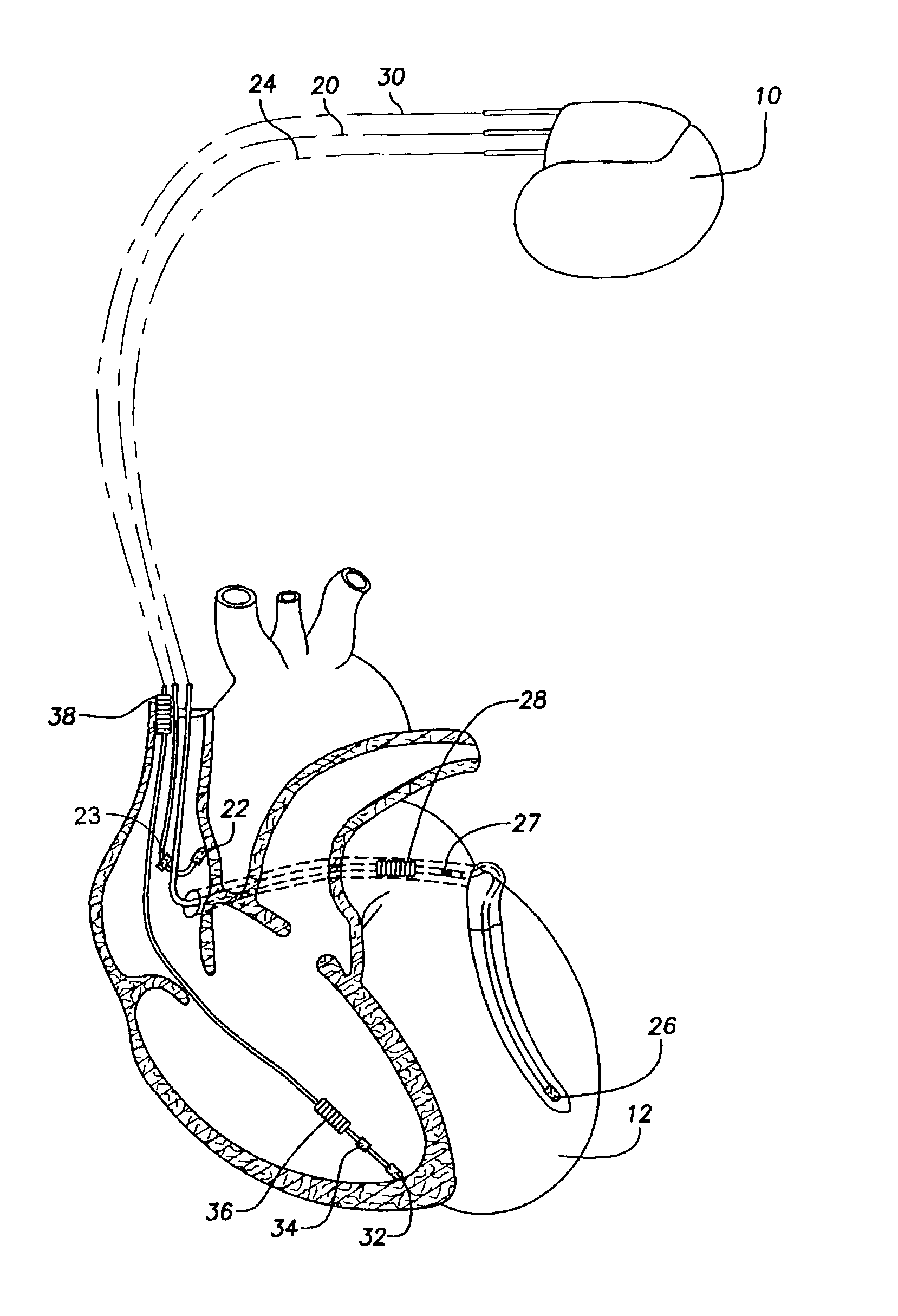
[0023]As shown in FIG. 3, there is a stimulation device 10 in electrical communication with the heart 12 of a patient by way of three leads, 20, 24 and 30, suitable for delivering multi-chamber stimulation and shock therapy. To sense atrial cardiac signals and to provide right atrial chamber stimulation therapy, the stimulation device 10 is coupled to an implantable right atrial lead 20 having at least an atrial tip electrode 22, which typically is implanted in the righ...


PUM


Abstract

A technique is provided for filtering far-field electrical cardiac signals from near-field signals. Atrial tip and ring signals are sensed using unipolar electrodes and any timing differences between corresponding events within the signals are detected. Then, far-field signals are filtered from the tip and ring signals based on the detected timing differences, such that substantially only near-field atrial signals remain. The technique exploits the fact that near-field atrial signals are sensed when a conduction wave passes by the atrial electrodes. In contrast, far-field signals from the ventricles propagate to the atrium at near the speed of light. Hence, any significant timing difference between corresponding events appearing in the atrial signals is indicative of a near-field event, whereas the lack of a significant timing difference is indicative of a far-field event. In one example, a sense amplifier is provided with a Boolean logic circuit to aid in time delay-based filtering.

Description

FIELD OF THE INVENTION[0001]The invention generally relates to implantable cardiac stimulation devices such as pacemakers and implantable cardioverter / defibrillators (ICDs) and, in particular, to techniques for rejecting far-field ventricular signals from cardiac signals sensed in the atria.BACKGROUND OF THE INVENTION[0002]Many pacemakers and ICDs include one or more leads mounted in the atria for directly sensing atrial events, particularly P-waves. Reliable P-wave detection is required so as to determine the atrial rate for detecting atrial fibrillation and for controlling atrial pacing functions, such as dynamic atrial overdrive (DAO) pacing. A long-standing problem with atrial sensing is that electrical signals generated in the ventricles often appear within the atrial signals and can be misinterpreted as P-waves. The signals from the ventricles are referred to as far-field signals. Indeed, because the ventricles are considerably more massive than the atria, depolarization of ve...

Claims


Application Information

Patent Timeline
Patent Type & Authority Patents(United States)
IPC IPC(8): A61N1/05
CPCA61N1/368A61N1/056A61N2001/0585
Inventor KROLL, MARK W.BOILEAU, PETER
Owner PACESETTER INC
Why Eureka
Try Eureka