
Firearm hammer with adjustable spur

Active Publication Date: 2006-11-28
SMITH & WESSON
View PDF4 Cites 48 Cited by
  • Summary
  • Abstract
  • Description
  • Claims
  • Application Information

AI Technical Summary

Benefits of technology

[0003]Telescopic sights such as rifle telescopes and pistols scopes may be mounted on a wide variety of firearms. It is desirable to mount a scope low, close to the bore of a gun's barrel. This provides a more compact form, and reduces inaccuracies due to the offset between the scope axis and the barrel axis. A low scope mounting position also allows a comfortable fit and eye relief for the shooter. However, in many applications, positioning the scope where desired may interfere with operation of the hammer. Normally, this does not necessarily mean that the scope blocks the path of the hammer spur, but that clearance is limited. This can make it difficult for the shooter to position his thumb above the spur as needed to cock the hammer. Depending on the clearance, the cocking operation may be difficult, painful, or impossible.
[0005]In addition, add-on pieces can cause a hammer spur to fracture due to the stresses during firing. Moreover, the added mass reduces the “lock time”, which is the time it takes the hammer to fall through its path during firing, decreasing accuracy.
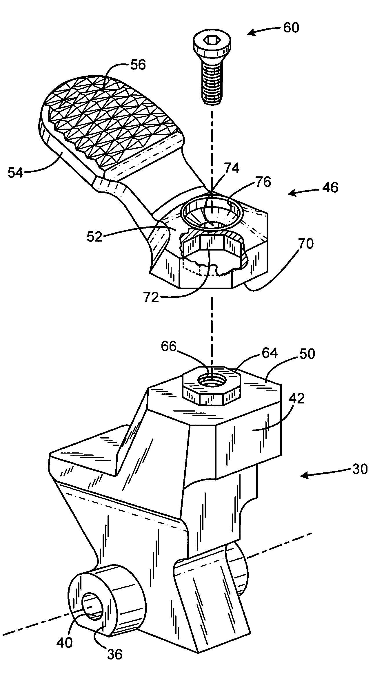
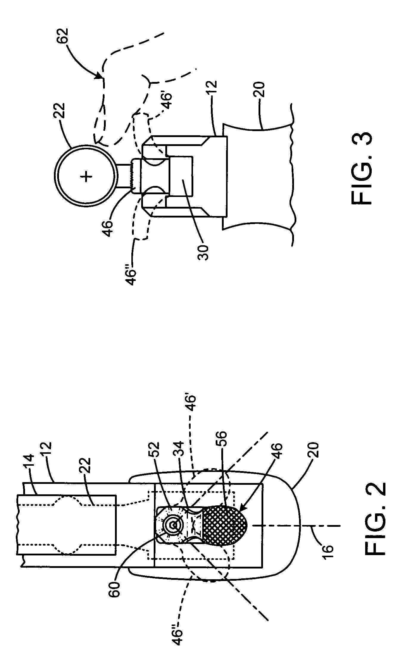
[0006]The present invention overcomes the limitations of the prior art by providing a firearm hammer having a hammer body with a hammer pivot axis for attachment to a firearm frame. A spur is connected to the hammer body, and the spur is movable among a number of positions with respect to the hammer body. The spur may be attached in a standard position in which it extends within the medial plane of the hammer body for use without a scope, or offset positions in which it angles away from the medial plane to provide accessibility. The offset angle may be 45 degrees, and a mating feature may provide the several attachment positions, each secure against movement except by deliberate removal of a fastener.

Problems solved by technology

However, in many applications, positioning the scope where desired may interfere with operation of the hammer.
Normally, this does not necessarily mean that the scope blocks the path of the hammer spur, but that clearance is limited.
This can make it difficult for the shooter to position his thumb above the spur as needed to cock the hammer.
Depending on the clearance, the cocking operation may be difficult, painful, or impossible.
First, as an accessory piece, even an extension post included with the purchase of a firearm may be lost by the time the owner later acquires a scope for the firearm.
More importantly, the perpendicularly protruding post is not only readily contacted by the shooter's thumb, but also by brush or other objects such as clothing to unintentionally cock the firearm.
This creates a serious safety problem, because a hunter may wrongly assume that because he has not manually cocked his gun, it is safe for carrying about in the field, when in fact the gun has been unknowingly cocked by contact with brush and is ready to fire.
In addition, add-on pieces can cause a hammer spur to fracture due to the stresses during firing.
Moreover, the added mass reduces the “lock time”, which is the time it takes the hammer to fall through its path during firing, decreasing accuracy.

Method used


Image

  • Firearm hammer with adjustable spur
  • Firearm hammer with adjustable spur
  • Firearm hammer with adjustable spur

Examples


Embodiment Construction

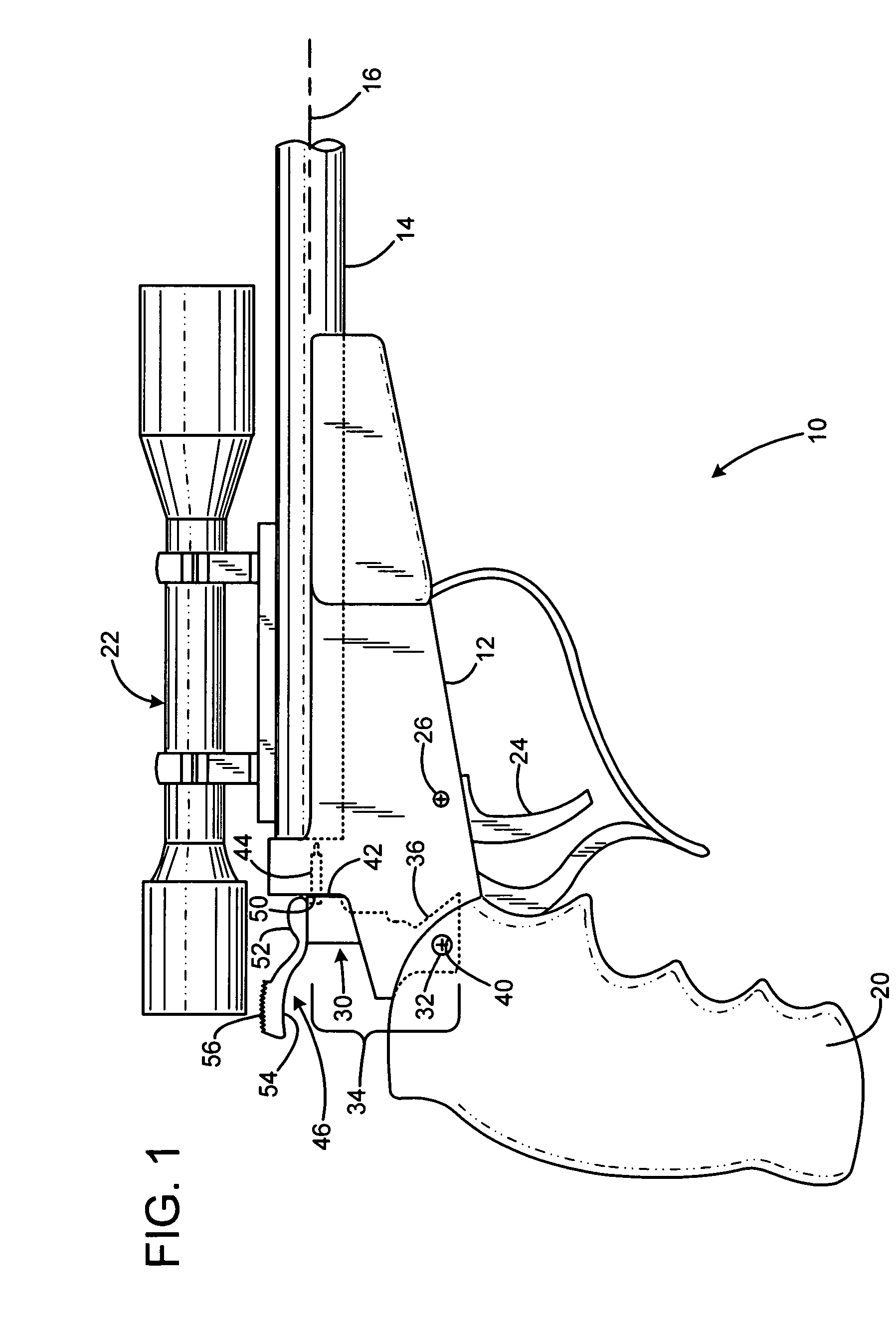
[0012]FIG. 1 shows a firearm 10 such as a single shot target or hunting pistol. The pistol includes a frame 12, a barrel 14 defining a barrel axis 16 and mounted to the frame, and a grip 20 mounted to the frame. A telescopic sight 22 is mounted to the barrel, with an optical axis essentially parallel to the barrel axis. A trigger lever 24 is pivotally attached to the frame for pivoting about a trigger axis 26 that is transverse to the frame, and perpendicular to the barrel axis. Similarly, a hammer assembly 30 is pivotally connected to the frame for pivoting about a hammer pin 32 that defines a hammer pivot axis. The hammer assembly is movable between a rear cocked position (not shown) and the forward uncocked or fired position shown. The hammer is biased to the fired position by the action of a spring (not shown).

[0013]The hammer assembly has a main body 34 including a lower portion 36 defining a pivot hole 40 for receiving the pivot pin. The hammer body 34 has a forward facing str...


PUM


Abstract

A firearm hammer has a hammer body with a hammer pivot axis for attachment to a firearm frame. A spur is connected to the hammer body, and the spur is movable among a number of positions with respect to the hammer body. The spur may be attached in a standard position in which it extends within the medial plane of the hammer body for use without a scope, or offset positions in which it angles away from the medial plane to provide accessibility. The offset angle may be 45 degrees, and a mating feature may provide the several attachment positions, each secure against movement except by deliberate removal of a fastener.

Description

FIELD OF THE INVENTION[0001]This invention relates to firearms, and more particularly to hammers for firearms with telescopic sights.BACKGROUND AND SUMMARY OF THE INVENTION[0002]Many firearms including pistols, rifles, and specialized single shot firearms are hammer fired. The hammer is a pivoting element near the breech of the gun barrel that is drawn back against spring tension, then is released upon pulling the trigger. A forward face of the hammer pivots forward to strike the rear of a firing pin (or may itself including a firing pin) to strike the primer of a cartridge, or any ignition device used in muzzleloading firearms. The hammer typically has a spur, which is an extension that protrudes upward and / or rearward when the hammer is in the forward position, and which is engaged by the shooter's thumb to pull the hammer rearward to a coked position in preparation for the next shot. Some firearms such as single-action revolvers and certain single shot pistols and rifles, includi...

Claims


Application Information

Patent Timeline
IPC IPC(8): F41A3/00
CPCF41A19/14F41A17/74
Inventor LANEY, MARK C.CATE, GORDON R.
Owner SMITH & WESSON
Learn More