
Method of and apparatus for applying adhesive to running webs of paper and the like

a technology of running webs and adhesives, applied in the field of methods and apparatus for applying adhesive to running webs of paper and the like, can solve the problems of contaminating the tipping machine, affecting the segregation of smokers' products, and affecting the safety of the tipping machin

Inactive Publication Date: 2006-11-28
HAUNI MASCHINENBAU AG
View PDF31 Cites 6 Cited by
  • Summary
  • Abstract
  • Description
  • Claims
  • Application Information

AI Technical Summary

Benefits of technology

The present invention provides a novel and improved method of applying a flowable adhesive to running webs of cigarette paper, tipping paper, or the like, which reduces the likelihood of penetration of the adhesive from one side to the other side of the paper during and after application. This method also allows for the regulation of the amount of adhesive used as a function of various parameters that influence the bonding action. Additionally, the invention provides an apparatus for carrying out this method and a method of making a filter for tobacco smoke. The technical effects of this invention include improved efficiency in applying adhesive, reduced risk of weak or unsatisfactory connections between parts, and improved quality of the bond.

Problems solved by technology

A drawback of the conventional adhesive applying methods and apparatus is that the adhesive substance often penetrates through the web of wrapping material and contaminates those portions of a filter rod making or filter tipping machine which come into contact with the adhesive.
Moreover, the adhesive at the outer side of the tubular envelope affects the appearance of the filter cigarette, cigar or cigarillo and renders it necessary to segregate such smokers' products from acceptable smokers' products.
The adhesive which has penetrated through the cigarette paper as well as through the tipping paper is likely to contaminate the tipping machine and to necessitate segregation of numerous filter cigarettes between the maker of such products and the packing machine.

Method used


Image

  • Method of and apparatus for applying adhesive to running webs of paper and the like
  • Method of and apparatus for applying adhesive to running webs of paper and the like
  • Method of and apparatus for applying adhesive to running webs of paper and the like

Examples


Embodiment Construction

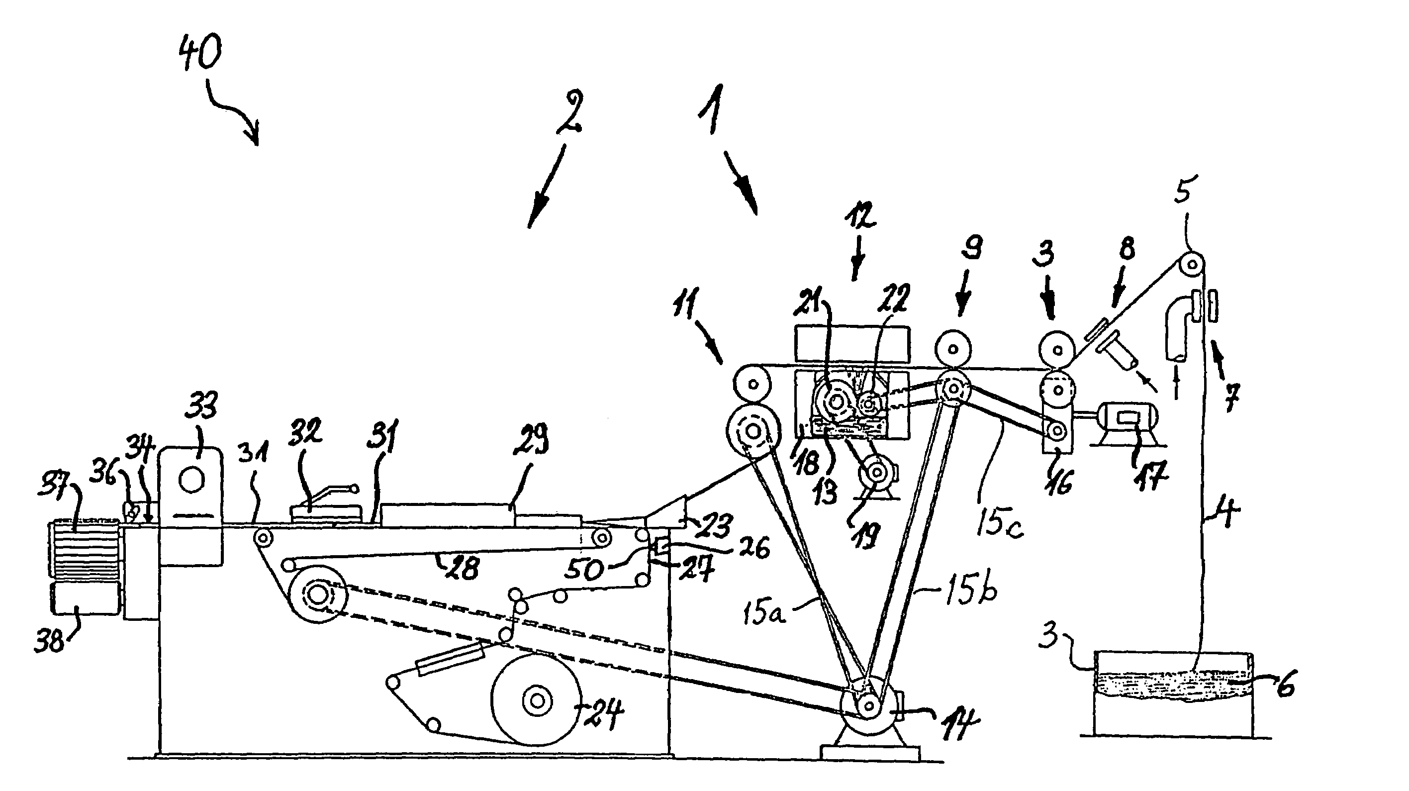
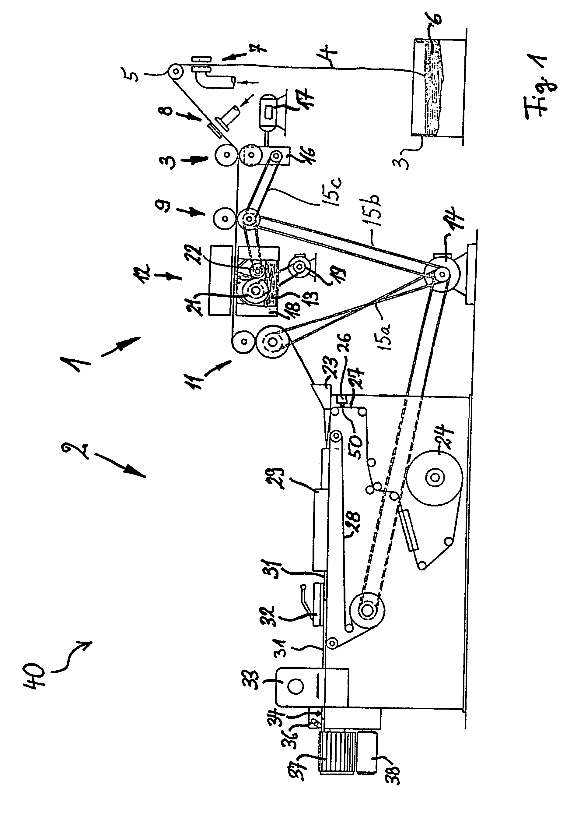
[0037]FIG. 1 shows certain details of a filter rod making machine 40 of the type disclosed in the aforementioned U.S. Pat. No. 3,974,007 (Greve) and U.S. Pat. No. 4,412,505 (Häusler et al.). The machine 40 comprises a filter tow processing unit or section 1 and a filter rod making section or unit 2. The unit 1 includes a receptacle 3 for a bale 6 of a tow 4 of filamentary filter material (such as crinkled acetate fibers). The tow 4 is continuously pulled lengthwise by a pair of driven rolls 3 which cause successive increments of the tow to advance through a first so-called banding (tow spreading and loosening) device 7, around a deflecting roller 5, and through a second banding device 8 which is or which can be identical with the device 7. The rolls 3 are followed by two additional pairs of advancing rolls 9 and 11. The rolls 9 are driven at a peripheral speed exceeding that of the rolls 3 so that the filaments of the tow 4 are stretched between the rolls 3 and 9 to a degree selecte...


PUM


Abstract

A novel and improved method of applying adhesive to one side of a running web of wrapping material for a rod-like filler of filter material for tobacco smoke includes directing toward the one side of the web a stream of adhesive which issues from an open-and-shut orifice of a nozzle, and employing one or more jets of compressed air to vary the direction of flow of the stream so that the adhesive coats one marginal portion as well as the adjacent portion of the major central part of the one side and forms at least one non-linear layer. Once the thus treated web is draped around the filler, the adhesive bonds the two marginal portions of the converted web to each other and simultaneously bonds the central part of the web to the filler.

Description

CROSS-REFERENCE TO RELATED CASES[0001]This application claims the priority of the commonly owned copending German patent application Serial No. 100 27 955.4 filed Jun. 8, 2000. The disclosure of such German patent application, as well as that of each U.S. and / or foreign patent and patent application identified in the specification of the present application, is incorporated herein by reference.BACKGROUND OF THE INVENTION[0002]The invention relates to improvements in methods of and in apparatus for applying flowable substances to running webs or strips of wrapping material in rod making machines, especially in rod making machines of the tobacco processing industry. Typical examples of such machines are so-called filter rod making machines which serve to make continuous rods of wrapped filter material for tobacco smoke. The rod is subdivided into filter rod sections of unit length or multiple unit length which can be fed to a so-called tipping machine wherein the filter rod sections a...

Claims


Application Information

Patent Timeline
Patent Type & Authority Patents(United States)
IPC IPC(8): B65B61/00B31B1/62B31C13/00A24C5/18A24C5/24A24F13/06B05B7/06B05C5/00B05D7/00B05D7/24B31B50/62B31C99/00
CPCA24C5/24
Inventor FIETKAU, STEFAN
Owner HAUNI MASCHINENBAU AG
Learn More