
Glue injection joint accessory for large-diameter composite hose

A composite hose and large-diameter technology, applied in the direction of pipes/pipe joints/fittings, hose connection devices, mechanical equipment, etc., can solve the problems of loss of sealing performance, joint falling off, high cost, etc., to reduce the possibility of penetration, Guaranteed strength and tightness, and the effect of preventing corrosion

Active Publication Date: 2015-03-25
WUDI HAIZHONG FLEXIBLE PIPE MFG CO LTD
View PDF5 Cites 0 Cited by
  • Summary
  • Abstract
  • Description
  • Claims
  • Application Information

AI Technical Summary

Problems solved by technology

[0003] Traditional and conventional submarine pipelines are mainly made of steel pipes, and the hoses have long relied on foreign imports. The overall construction, installation and follow-up maintenance work cycle is long and expensive. The advantages of strong adaptability, fast laying speed, low cost, not easy to deposit wax and can be reused have begun to be applied to the transportation of subsea oil, gas and water. Due to the limited continuous length of the hose pipeline, each hose end must be equipped with Joint fittings are used to ensure the connection between pipelines. However, with the continuous improvement of the production technology level of domestic composite hoses and the trend of offshore oil and gas exploration to the deep sea, composite hoses have broad prospects for application in offshore oil and gas pipelines.
With the increase of hose pressure and caliber, the sealing performance, strength and service life of traditional small-bore hose buckle-type joints and glue-injection joints can no longer meet the requirements of use.
As the temperature and pressure of the medium conveyed by the composite hose change, each layer of the hose will expand and contract to varying degrees, and the reciprocating cycle is likely to cause the joint to fall off or lose its sealing performance

Method used


Image

  • Glue injection joint accessory for large-diameter composite hose
  • Glue injection joint accessory for large-diameter composite hose

Examples


Embodiment Construction

[0018] The present invention will be described in detail below in conjunction with the accompanying drawings and examples.

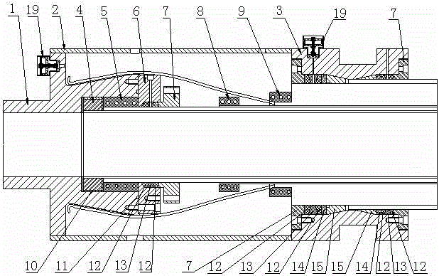
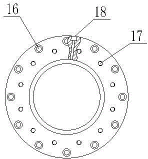
[0019] Such as figure 1 , 2 As shown, the present invention includes a joint front end 1, a joint jacket 2, a joint rear end 3, a fixing ring 4, a fixing sleeve 5, a fastening flange 6, a sealing flange 7, a tight sleeve 8, a clamping block 9, and an insulating pad 10. O-ring 11, sealing ring 12, steel ring 13, steel sleeve 14 and tapered sleeve 15. Put the sealing flange 7, sealing ring 12, steel ring 13, sealing ring 12, steel sleeve 14, tapered sleeve 15, and joint rear end 3 into the outer cladding layer of the composite hose in sequence, and pass the high-strength bolts through the sealing method Screw the through hole of flange 7 into the threaded hole 3 at the rear end of the joint, and the sealing ring 12 is deformed to achieve sealing; the tapered sleeve 15, steel sleeve 14, sealing ring 12, steel ring 13, sealing ring 12, and sealing flan...


PUM


Abstract

The invention relates to a glue injection joint accessory for a large-diameter composite hose. The glue injection joint accessory comprises a joint front end, a joint jacket, a joint rear end, a fixing ring, a fixing sleeve, a fastening flange, a seal flange, a holding sleeve, a clamping block, an insulating pad, an O-shaped ring, a seal ring, a steel ring, a steel bushing and a conical sleeve. By components mechanically fixed to each layer of the composite hose, mechanical fixation between each layer of the composite hose and the joint accessory can be realized, sealing of an inner pressure seal layer, an outer coating layer and a middle coating layer of the composite hose is guaranteed, and possibility of permeation of a joint is lowered; by the aid of exhaust valves in two specifications, a solution to discharge of permeation gas when the exhaust valve at the front end of the joint is in blockage is realized; owing to the insulating pad, corrosion is avoided, and strength and airtightness of the composite hose are guaranteed.

Description

[0001] technical field [0002] The invention relates to a pipeline joint fitting, in particular to a glue injection joint fitting used for a marine large-diameter composite hose. Background technique [0003] Traditional and conventional submarine pipelines are mainly made of steel pipes, and the hoses have long relied on foreign imports. The overall construction, installation and follow-up maintenance work cycle is long and expensive. The advantages of strong adaptability, fast laying speed, low cost, not easy to deposit wax and can be reused have begun to be applied to the transportation of subsea oil, gas and water. Due to the limited continuous length of the hose pipeline, each hose end must be equipped with Joint fittings are used to ensure the connection between pipelines. However, with the continuous improvement of domestic composite hose production technology and the trend of offshore oil and gas exploration to the deep sea, composite hoses have broad prospects for ...

Claims


Application Information

Patent Timeline
IPC IPC(8): F16L33/02
CPCF16L33/01
Inventor 王翎羽梁威冯岩
Owner WUDI HAIZHONG FLEXIBLE PIPE MFG CO LTD
Learn More