
Gas turbine engine with intake air flow control mechanism

a technology of air flow rate control and gas turbine engine, which is applied in the direction of machines/engines, liquid fuel engines, lighting and heating apparatus, etc., can solve the problems of difficult enlargement of the operational range, difficult to control the flow rate of air, and the prescribed standard of exhaust gas may not be satisfied, so as to suppress the discharge of atmospheric pollutant and control stably

Active Publication Date: 2006-11-28
KAWASAKI HEAVY IND LTD
View PDF11 Cites 47 Cited by
  • Summary
  • Abstract
  • Description
  • Claims
  • Application Information

AI Technical Summary

Benefits of technology

[0008]An object of the present invention is to provide a gas turbine engine of a simple structure having an intake air flow control mechanism for stably controlling the air flow according to the load of an engine so as to maintain the air-to-fuel ratio of a combustor within a proper range suited to suppress a discharge of an atmospheric pollutant.
[0010]In such a constitution, the intake air flow to the compressor can be controlled stably according to the load of the engine. Moreover, by the intake air flow control, the air-to-fuel ratio is controlled within a range suited to suppress a discharge of an atmospheric pollutant according to the load of the engine, so that the exhaust gas standard can be satisfied. Further, the air flow control system is installed in the air intake path, which is located outside and upstream with respect to the compressor, so that there is no need to arrange the air flow control system inside the engine, thus a simple structure can be obtained.
[0012]In such a constitution, the air intake duct is connected to the inlet of the compressor as an ancillary element of the main body of the gas turbine engine including the compressor, the combustor, and the turbine, and the air flow control system can be just installed to the air intake duct. Thereby, there is no need to change the structure of the main body of the engine, thus the structure can be simplified and the manufacturing cost can be decreased. Further, only by simply modifying the air intake duct, the air flow control system can be installed to an existing gas turbine engine, so that the cost for modification can be decreased.

Problems solved by technology

However, when an operable load range of a generator is enlarged, the generator may be operated at an air-to-fuel ratio outside the proper range thereof suited to suppress a discharge of an atmospheric pollutant from a gas turbine engine, thereby the prescribed standard of exhaust gas may not be satisfied.
Thus, it is difficult to enlarge the operational range with satisfying the prescribed exhaust gas standard.
However, the air flow control mechanism is complicated in its structure and expensive and moreover, the combustor is provided with a bypass flow path so that the structure inevitably increases in size.

Method used


Image

  • Gas turbine engine with intake air flow control mechanism
  • Gas turbine engine with intake air flow control mechanism
  • Gas turbine engine with intake air flow control mechanism

Examples


Embodiment Construction

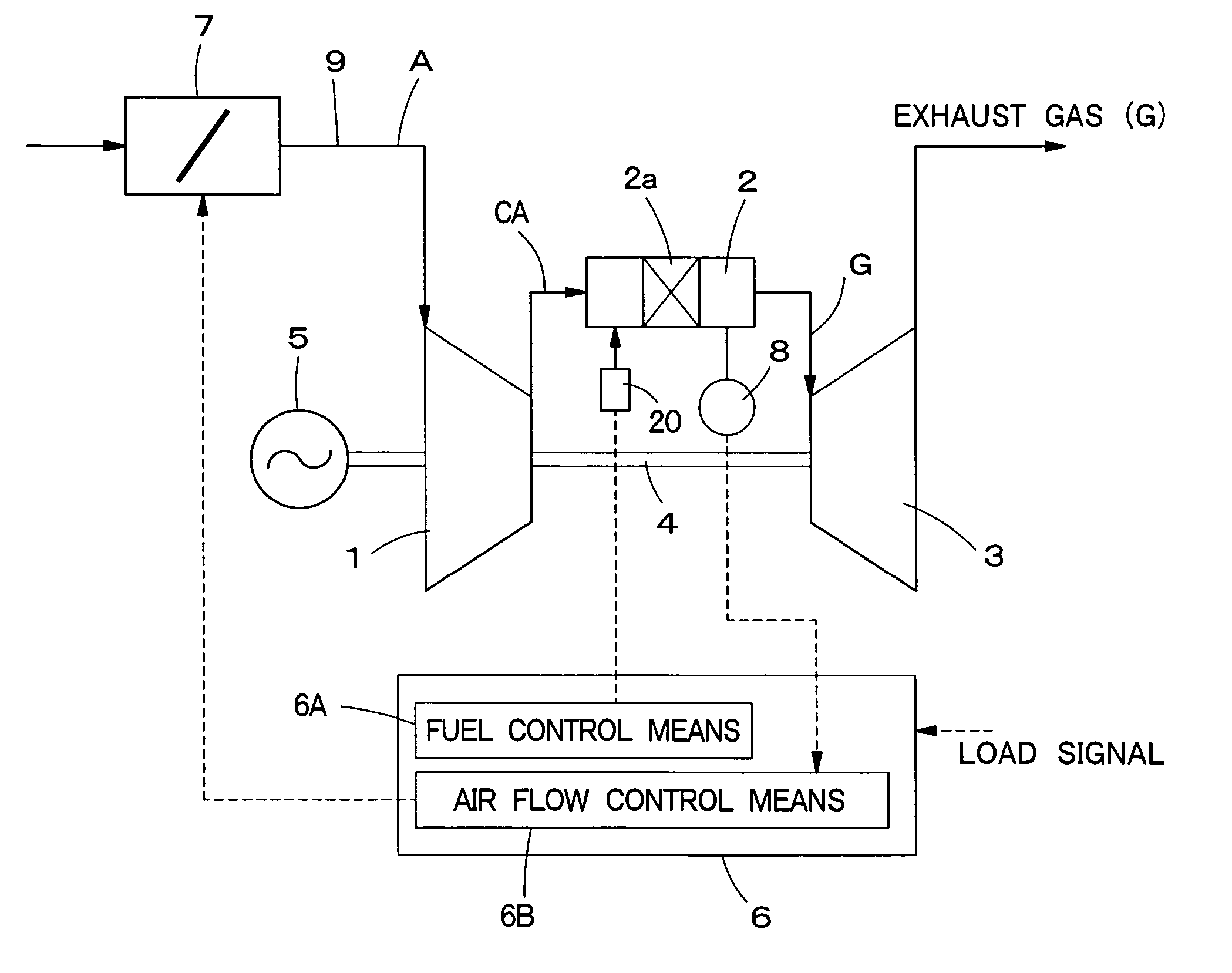
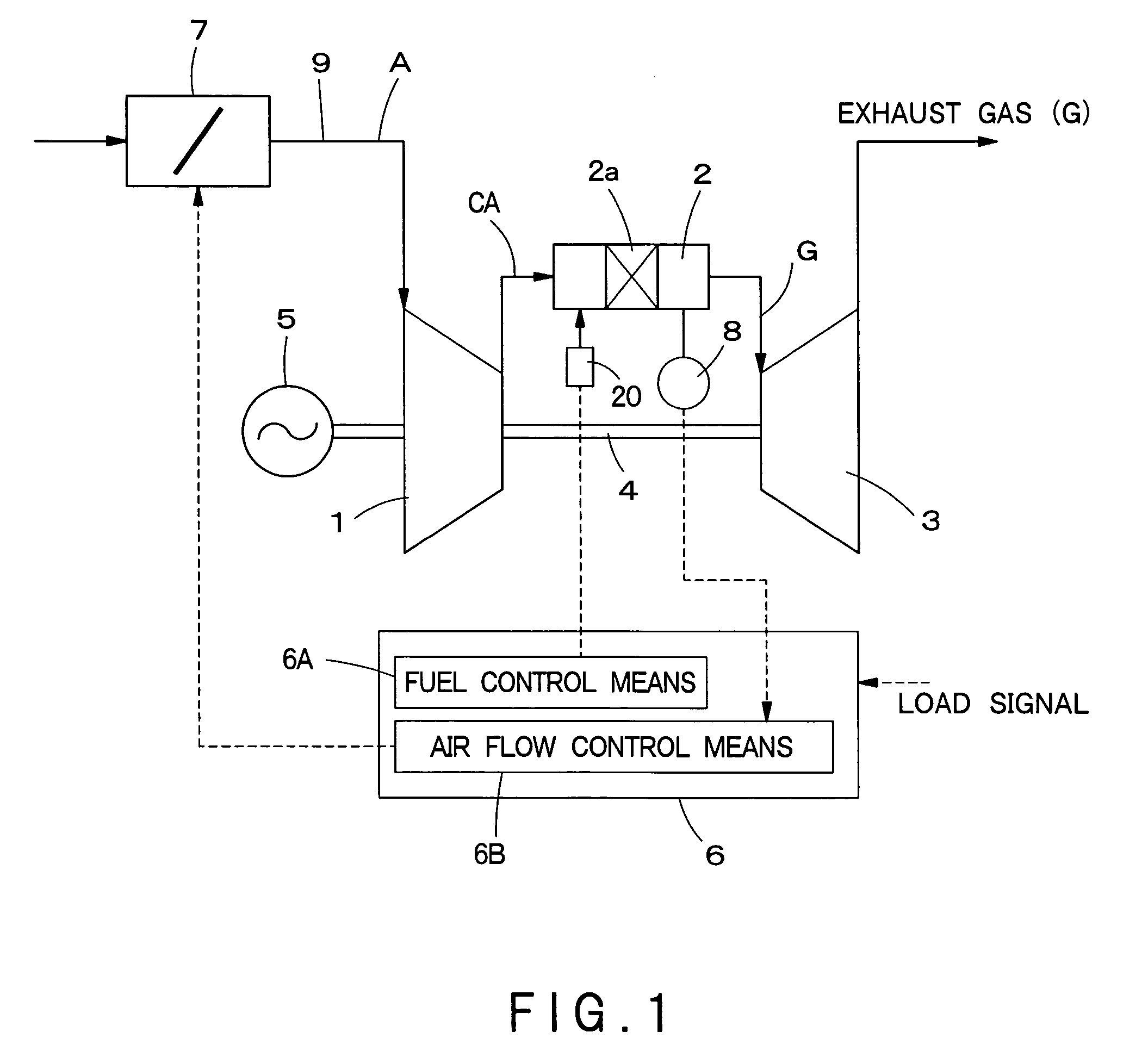
[0031]In this first embodiment shown in FIG. 1, the combustor of the gas turbine engine is a catalytic combustor having a built-in catalyst.

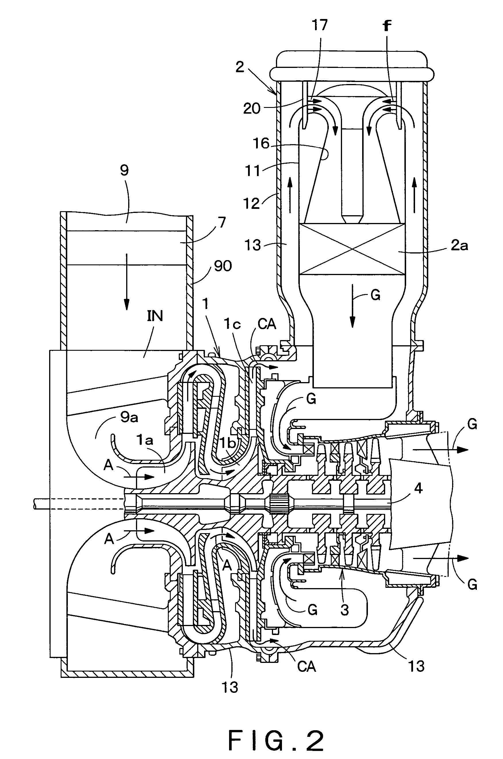
[0032]The gas turbine engine of the present embodiment has a compressor 1 for sucking in and compressing air A, a catalytic combustor 2 with a built-in catalyst 2a for feeding fuel to compressed air CA compressed by the compressor 1 and burning it in the catalyst 2a, and a turbine 3 to be rotated by combustion gas G generated by the catalytic combustor 2. The compressor 1 connected to the turbine 3 via a revolving shaft 4 and a generator 5 as an example of a rotation load are driven by the rotation of the turbine 3. The combustion gas G passes through the turbine 3 and is discharged outside as exhaust gas. In the intake air flow path for feeding the air A to the compressor 1, an air flow control system 7 is installed.

[0033]An engine control unit 6 controls the engine so as to maintain the air-to-fuel ratio of the catalytic combustor 2 within the...


PUM


Abstract

A gas turbine engine includes: an air flow control system installed in an air intake path for introducing air to a compressor. The air intake path is located outside and upstream with respect to the compressor. The engine also includes intake air flow control means for controlling an intake air flow by operating the air flow control system according to a load of the engine so as to maintain an air-to-fuel ratio in the combustor within a proper range suited to suppress a discharge of an atmospheric pollutant.

Description

BACKGROUND OF THE INVENTION[0001]1. Field of the Invention[0002]The present invention relates to a gas turbine engine with an intake air flow rate control mechanism for controlling the intake air flow rate according to operational conditions to burn gas.[0003]2. Description of the Related Art[0004]To suppress the discharge of an atmospheric pollutant such as NOx and CO from a gas turbine engine, there are various types of combustors. On the other hand, there is a strong demand from users of gas turbine generators for enlarging the operable load range thereof. However, when an operable load range of a generator is enlarged, the generator may be operated at an air-to-fuel ratio outside the proper range thereof suited to suppress a discharge of an atmospheric pollutant from a gas turbine engine, thereby the prescribed standard of exhaust gas may not be satisfied.[0005]For example, for a gas turbine engine which is provided with a lean premixing combustor, there is a demand from users f...

Claims


Application Information

Patent Timeline
IPC IPC(8): F02C9/20F02C7/057F02C9/16F23R3/30F23R3/40
CPCF02C7/057F02C9/50F23R3/26F05D2270/08
Inventor HOSOKAWA, YASUFUMIGOUDA, MAKOTOOGATA, MASAHIRO
Owner KAWASAKI HEAVY IND LTD
Learn More