Acoustic wave flow sensor

a flow sensor and acoustic wave technology, applied in the direction of volume/mass flow measurement, measurement devices, instruments, etc., can solve the problems of unmet or met, flow sensors generally face potential degradation problems, and expensive, frequent cleaning or replacement of sensors, etc., to achieve high strain/stress sensitivity

Inactive Publication Date: 2006-11-28
HONEYWELL INT INC
View PDF18 Cites 6 Cited by
  • Summary
  • Abstract
  • Description
  • Claims
  • Application Information

AI Technical Summary

Benefits of technology

[0020]The aforementioned aspects of the invention and other objectives and advantages can now be achieved as described herein. An acoustic wave flow sensor is disclosed, which includes a sensor substrate and an acoustic wave diaphragm etched upon the sensor substrate, wherein mechanical stress or strain is concentrated in the acoustic wave diaphragm. One or more interdigital transducers can be configured upon the acoustic wave diaphragm, wherein the sensor substrate, the acoustic wave diaphragm and the interdigital transducer(s) form an acoustic wave flow sensor, such that when the interdigital transducer and the acoustic wave diaphragm are exposed to a fluid in flow, the fluid in flow causes the acoustic wave diaphragm to experience a change in the mechanical stress or strain resulting in a detectable frequency change in order to provide an indication of the fluid in flow. Additionally, the fluid in flow causes the acoustic wave diaphragm to experience a change in the mechanical stress or strain resulting in a detectable phase change in order to provide an indication of the fluid in flow.

Problems solved by technology

Such flow sensors generally face potential degradation problems when exposed to harsh (contaminated, dirty, condensing, etc.) fluids, including gases or liquids that can “stress” the sensor via corrosion, radioactive or bacterial contamination, overheating, or freeze-ups.
The sensitive measurement of the flow, or pressure (differential or absolute) of “harsh” gases or liquids that can stress corrode, freeze-up, or overheat the sensing elements is a challenge that is either unmet or met at great expense.
Frequent cleaning or replacement of the sensors is an additional, but costly, solution.
Sensitive, membrane-based differential pressure sensors can be protected against contamination because no flow is involved, but they are much less sensitive and much more expensive than thermal micro-sensors, in addition to not being overpressure proof.
Another problem with fluid or thermal flow sensors, particularly, micro-bridge thermal flow sensors, it that such devices possess a relative small dynamic range.
A micro-bridge thermal flow sensor, for example, typically incorporates a heater that consumes a great deal of power.
It is therefore difficult to adapt such devices for passive wireless applications.
An additional problem with thermal flow sensors is that heating may introduce unwanted chemical compositional change or damage the fluid (e.g., blood), particularly in medical applications.
This reduction in strength is known to be caused principally by surface flaws, such as scratches, which concentrate the applied stress and thereby lead to fracture at loads which are much lower than the theoretical maximum.
Etching does not introduce defects, but etching does reveal defects.
One of the problems with existing SAW flow sensor designs is that such configurations incorporate two or more SAW temperatures sensors along with a heater.
Such a design increases the sensor size and raises the production cost and power usage thereof.

Method used


Image

  • Acoustic wave flow sensor
  • Acoustic wave flow sensor
  • Acoustic wave flow sensor

Examples


Embodiment Construction

[0029]The particular values and configurations discussed in these non-limiting examples can be varied and are cited merely to illustrate at least one embodiment of the present invention and are not intended to limit the scope of the invention.

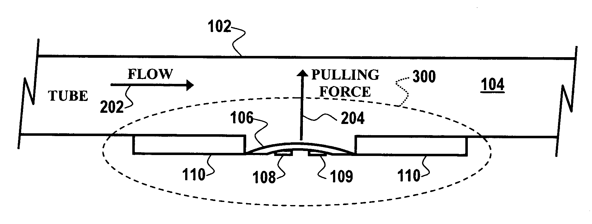
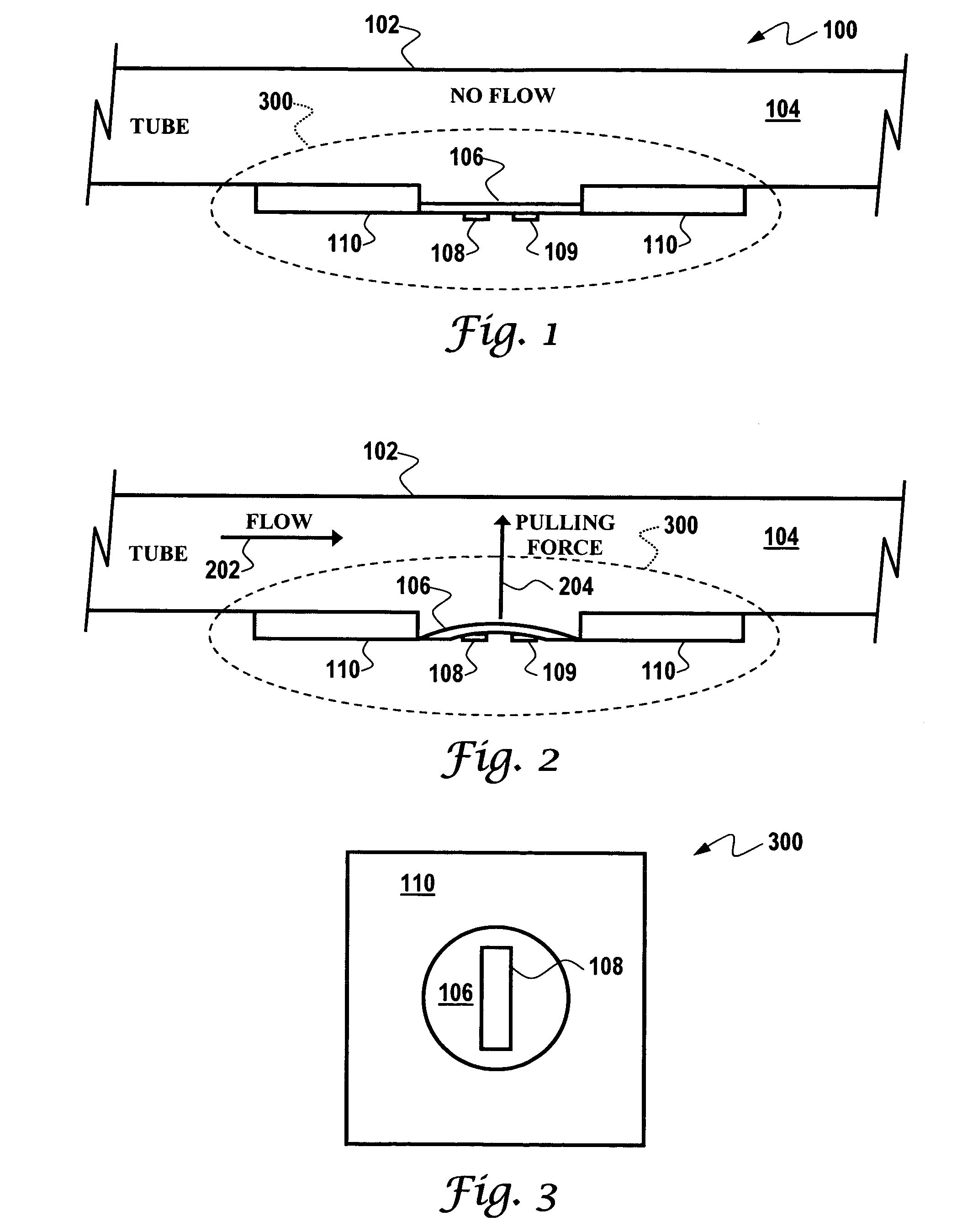
[0030]FIG. 1 illustrates a side view of a flow sensor system 100 that includes a SAW etched diaphragm 106 not under stress, in accordance with a preferred embodiment. FIG. 2 illustrates a side view of the flow sensor system 100 depicted in FIG. 1 with the SAW etched diaphragm 106 under stress, in accordance with a preferred embodiment. FIG. 3 illustrates a top view of a SAW sensor 300 with the SAW etched diaphragm 106 depicted in FIGS. 1–2, in accordance with a preferred embodiment. Note that in FIGS. 1–3, identical or similar parts or elements are generally indicated by identical reference numerals.

[0031]In the configuration of FIG. 1, system 100 is depicted with a tube 102 having a central portion 104 thereof, wherein fluid is not present or ...


PUM


Abstract

An acoustic wave flow sensor is disclosed, which includes a sensor substrate and an acoustic wave diaphragm etched upon the sensor substrate, wherein mechanical stress or strain is concentrated in the acoustic wave diaphragm. One or more interdigital transducers can be configured upon the acoustic wave diaphragm, wherein the sensor substrate, the acoustic wave diaphragm and the interdigital transducer(s) form an acoustic wave flow sensor, such that when the interdigital transducer and the acoustic wave diaphragm are exposed to a fluid in flow, the fluid in flow causes the acoustic wave diaphragm to experience a change in the mechanical stress or strain resulting in a detectable frequency and / or phase change in order to provide an indication of fluid flow.

Description

TECHNICAL FIELD[0001]Embodiments are generally related to flow sensing devices and techniques. Embodiments are also related to acoustic wave devices, such as, for example, surface acoustic wave (SAW) and bulk acoustic wave (BAW) devices.BACKGROUND OF THE INVENTION[0002]Flow sensors are utilized in a variety of fluid-sensing applications for detecting the quality of fluids, including gas and liquid. Flow sensors for such fluids, which detect the fluid flow or property of fluid, can be implemented, for example, as sensors on silicon in microstructure form. For convenience sake, and without limitation, the term “flow sensor” not only can refer to the flow of a fluid (including both gas and liquids), but can also be implemented in the context of thermal sensors. The reader will appreciate that such sensors may be also utilized to measure primary properties such as temperature, thermal conductivity, specific heat and other properties; and that the flows may be generated through forced or...

Claims


Application Information

Patent Timeline
Patent Type & Authority Patents(United States)
IPC IPC(8): G01F1/66
CPCG01F1/662
Inventor LIU, JAMES Z TRAHMAN, AZIZ
Owner HONEYWELL INT INC
Why Eureka
Try Eureka