Swirl forming device in combustion engine

a technology of swirling and combustion engine, which is applied in the direction of combustion engine, machine/engine, fuel air intake, etc., can solve the problems of insufficient increase of combustion efficiency, difficulty in promoting vigorous and massive swirling motion, and inability to smoothly develop the swirling flow of the charge mixtur

Inactive Publication Date: 2006-11-28
KAWASAKI HEAVY IND LTD
View PDF9 Cites 49 Cited by
  • Summary
  • Abstract
  • Description
  • Claims
  • Application Information

AI Technical Summary

Benefits of technology

[0008]In view of the foregoing problems and inconveniences inherent in the conventional swirl forming devices, the present invention is intended to provide an improved swirl forming device in a combustion engine, which is effective to promote a vigorous and massive swirling motion of an intake gas within a combustion chamber of the engine.

Problems solved by technology

In other words, the air flowing through the bypass passages and then jetted into the combustion chamber from a position adjacent the outer periphery of the combustion chamber collides against the peripheral surface of the combustion chamber and the top face of a reciprocating piston and, therefore, no swirling flow of the charge mixture can be smoothly developed.
Thus, the conventional swirl forming device of the design discussed above acts to develop the swirl of the intake gas merely by biasing the flow of the intake gas (the air-fuel mixture and the air) being introduced into the combustion chamber through the intake valves and, therefore, it has been found difficult to promote a vigorous and massive swirling motion.
For this reason, with the conventional swirl forming device, the combustion efficiency cannot be sufficiently increased particularly when the lean air-fuel mixture is employed, and, therefore, hydrocarbons in the exhaust gas cannot be sufficiently reduced.

Method used


Image

  • Swirl forming device in combustion engine
  • Swirl forming device in combustion engine
  • Swirl forming device in combustion engine

Examples


first embodiment

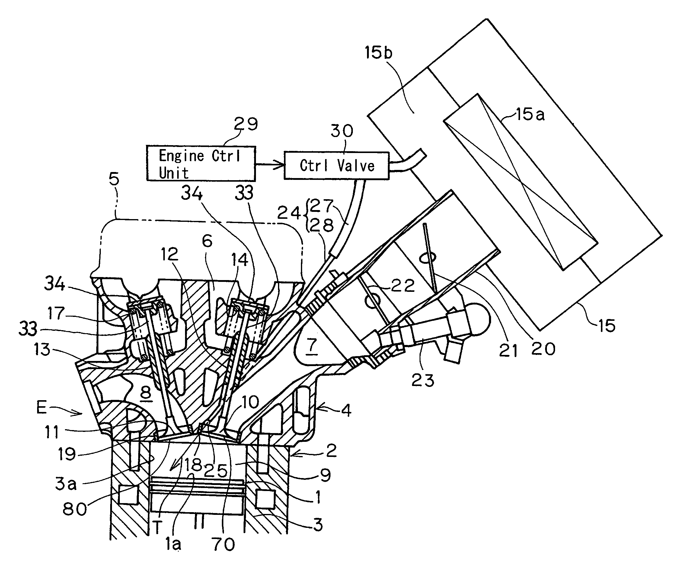
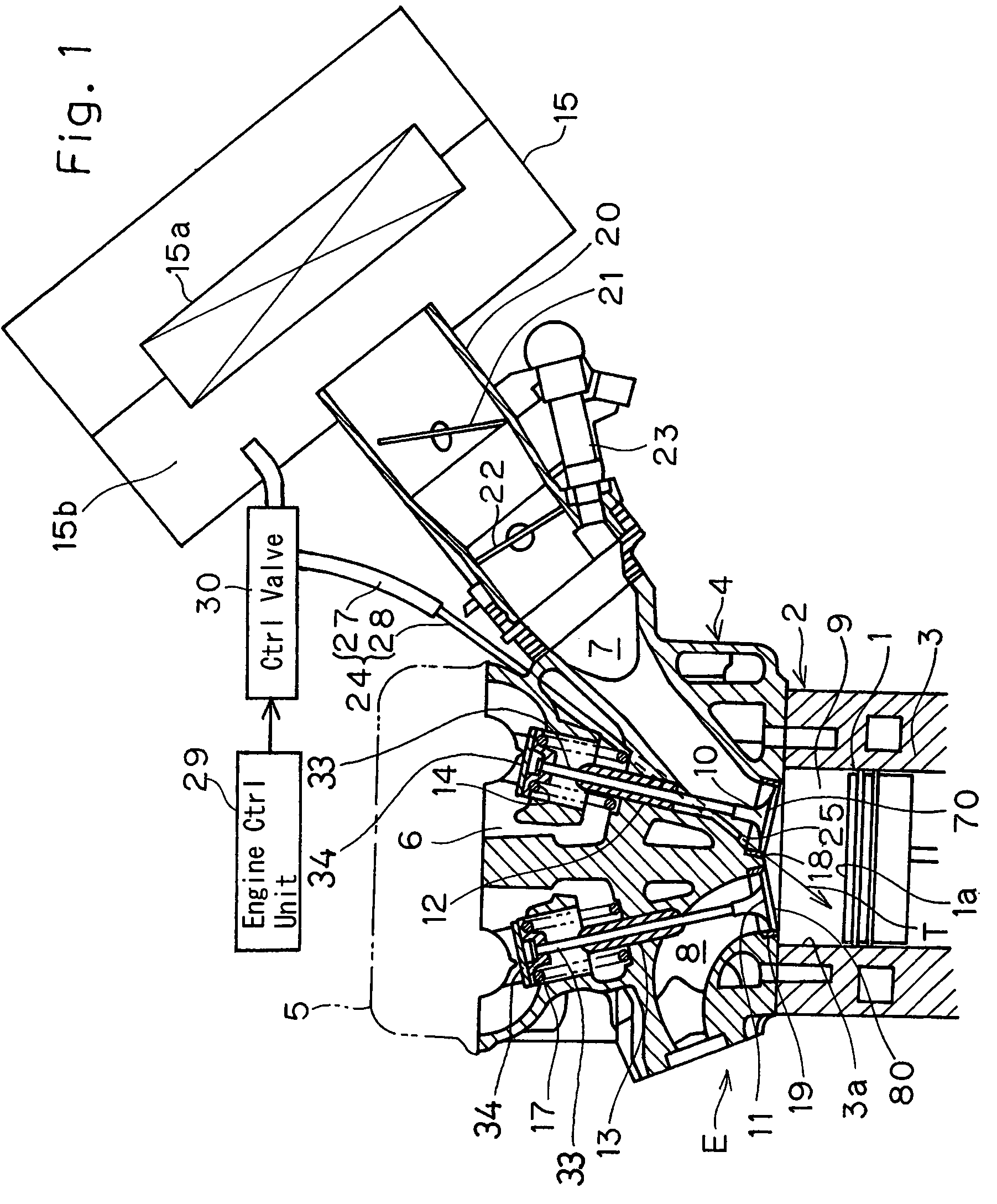
[0023]Referring particularly to FIG. 1 showing an essential portion of the combustion engine E, which incorporates the swirl forming device according to the present invention, the combustion engine E shown therein is assumed as mounted on, for example, a motorcycle and includes a cylinder block 2, fixedly mounted on a crankcase (not shown), a cylinder head 4 mounted atop the cylinder block 2, and a cylinder head cover 5 mounted on the cylinder head 4 and positioned on one side of the cylinder head 4 opposite to the cylinder block 2. The cylinder block 2 has a cylinder bore 3 defined therein, within which a reciprocating piston 1 moves up and down, with a combustion chamber 9 defined within the cylinder bore 3 and above the reciprocating piston 1. A space delimited between the cylinder head 4 and the cylinder head cover 5 provides a valve chamber 6, in which a valving mechanism of the engine is accommodated.

[0024]So far shown, the cylinder head 4 has a pair of intake ports 70 and a p...

second embodiment

[0048]Accordingly, even in this second embodiment, the vigorous and massive swirl S having a large radius of curvature traveling along the inner peripheral surface 3a can be formed within the combustion chamber 9 by the effect of the introduced intake gas, (the air-fuel mixture and the air) spreading in the oval pattern when viewed from top in a direction confirming to the longitudinal axis of the cylinder bore 3, as is the case with that in the foregoing embodiment. Hence, by the effect of the swirling energies of the swirl S of the intake gas, the intake gas within the combustion chamber 9 can be effectively mixed and, therefore, even at the low load engine operating condition, in which the intake gas is adjusted to the lean air-fuel mixture, a substantially homogeneous combustion of the intake gas takes place within the combustion chamber, with the combustion efficiency increased consequently, resulting in a satisfactory reduction of the exhaust emissions containing hydrocarbons....


PUM


Abstract

To provide an improved swirl forming device in a combustion engine, which is effective to promote a vigorous and massive swirling motion of the charge mixture within the combustion chamber, the swirl forming device includes an auxiliary passage (24) for introducing an auxiliary gas, which may be either air or a charge mixture, into the combustion chamber (9) from a location immediately upstream of the intake port (70) that is selectively opened and closed by the intake valve (10). This auxiliary passage (24) has an open end (25) positioned adjacent the exhaust port (80), such that when viewed from top in a direction conforming to the longitudinal axis (CC) of the cylinder bore (3), the auxiliary gas is introduced in a direction different from the direction (N) normal to the inner peripheral surface (3a) of the cylinder bore (3) to thereby form a swirl (S) along the inner peripheral surface (3a) of the cylinder bore (3).

Description

BACKGROUND OF THE INVENTION[0001]1. Field of the Invention[0002]The present invention relates to a swirl forming device in a combustion engine, which forms a swirling flow of the charge mixture (i.e., the air-fuel mixture) within the combustion chamber when the combustion engine is operated at a low load condition such as occurring during idling and abrupt deceleration.[0003]2. Description of the Prior Art[0004]An combustion engine which uses a lean mixture of fuel and air has long been known in the art. In this combustion engine operating with the lean air-fuel mixture, during a low load operating condition of the engine the lean air-fuel mixture is supplied and, at the same time, the swirl of the lean air-fuel mixture is developed within the combustion chamber, for the purpose of increasing combustion efficiency and, also, reducing fuel consumption.[0005]In recent years, a swirl forming device has been suggested for an combustion engine of a double intake valve type, in which two ...

Claims


Application Information

Patent Timeline
Patent Type & Authority Patents(United States)
IPC IPC(8): F02B31/04F02B31/08F02B31/00F02B31/02F02M35/10
CPCF02B31/04F02M23/04F02M35/10262Y02T10/146Y02T10/12
Inventor SUZUKI, KOZOFUKAMI, YOJIKUJI, YASUHIRO
Owner KAWASAKI HEAVY IND LTD
Why Eureka
Try Eureka