Vehicle body frame structure

a frame structure and vehicle technology, applied in the direction of roofs, transportation and packaging, vehicle arrangements, etc., can solve the problems of reducing affecting the service life of the vehicle, so as to achieve the effect of increasing the endurance strength of the vehicle body

Active Publication Date: 2006-11-28
MITSUBISHI MOTORS CORP
View PDF11 Cites 56 Cited by
  • Summary
  • Abstract
  • Description
  • Claims
  • Application Information

AI Technical Summary

Benefits of technology

[0019]The vehicle body frame structure of this invention provides a rigid skeleton obtained by connecting the reinforcement member and the body panel together, and the outer frame member is fixed to the skeleton, whereby the connection to the side body as a structural connection can be realized, and the endurance strength of the vehicle body can be increased.

Problems solved by technology

This poses a problem that from the viewpoint of durable strength of the vehicle body, the connection becomes one of the most fracturable parts.
However, such joining method using bolts can merely achieve reinforcement by means of plates or metal sheets which are small in cross-section effect, and hence the connection to the side body cannot still be considered as a structural connection.
The part of connection to the side body still remains one of the most fracturable parts, and entails a problem of providing a poor endurance strength of the vehicle body.
In other words, the prior art disclosed in Japanese Utility Model Registration No. 3089814 does not pay a particular attention to the necessity to achieve a structural connection.
This cannot be considered as a structural connection, and still entails a problem of a poor rigidity of the vehicle body.
With this arrangement, when a force is generated in the front body, more specifically, when input exerting in the height direction of the vehicle body is caused by vibration of a strut tower serving as a suspension tower, for instance, such force cannot reliably and adequately be introduced, resulting in a problem of fear that it is difficult to cope with torsion or bending.
That is, this prior art does not pay a special attention to the necessity of increasing the rigidity resisting the input to the strut tower.
This causes a problem that it is difficult to cope with the variety of vehicles.

Method used


Image

  • Vehicle body frame structure
  • Vehicle body frame structure
  • Vehicle body frame structure

Examples


first embodiment

[0029]With reference to the appended drawings, a vehicle body frame structure according to this invention will be explained.

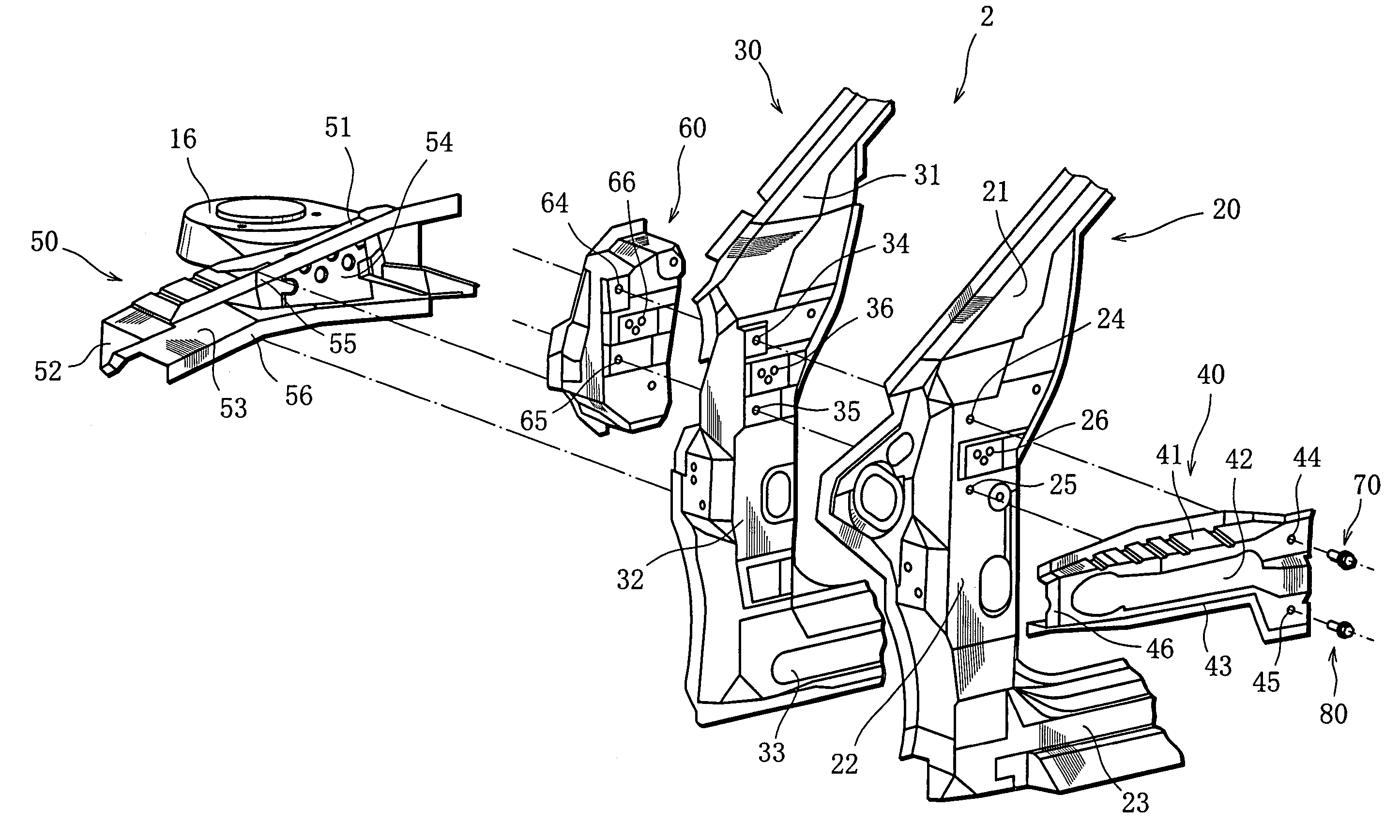
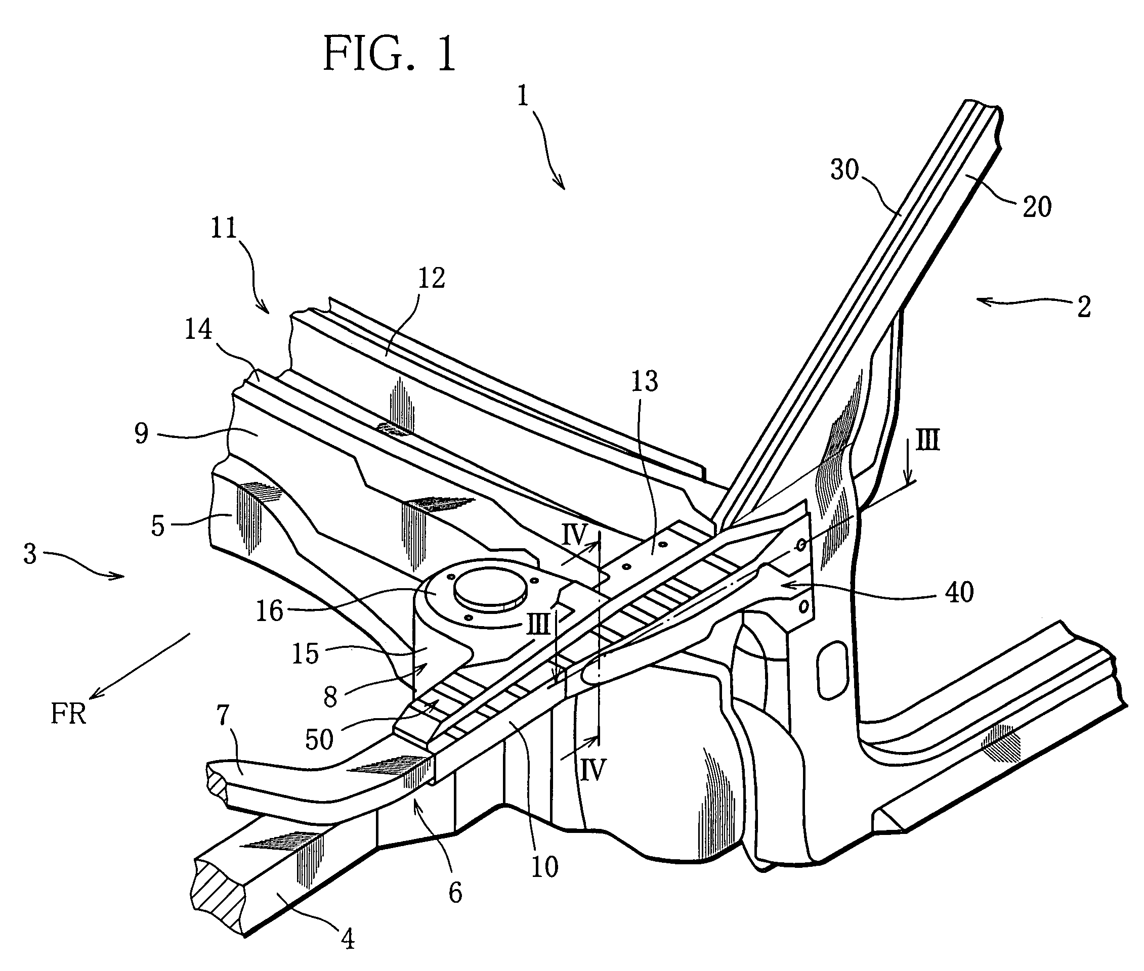
[0030]Referring to FIG. 1, a left-side vehicle body structure around an engine room of a sedan vehicle is shown in perspective view, which structure includes the vehicle body frame structure of this embodiment. FIG. 2 shows the vehicle body frame structure of FIG. 1 in fragmentary exploded perspective view. A vehicle body around the engine room will be explained with reference to FIGS. 1 and 2. Meanwhile, a right-side vehicle structure (not shown) is symmetrical to the left-side vehicle structure with respect to the vehicle center.

[0031]In a front body 3 around the engine room of the vehicle body 1, there are provided a pair of left and right front side members 4 which are coupled to each other by means of a front cross member (not shown) and a dash cross member 5 and to which lower portions of a pair of left and right hood ridges (front frame member) 6 are con...

second embodiment

[0047]Next, with reference to FIGS. 5–8, a vehicle body frame structure according to this invention will be explained.

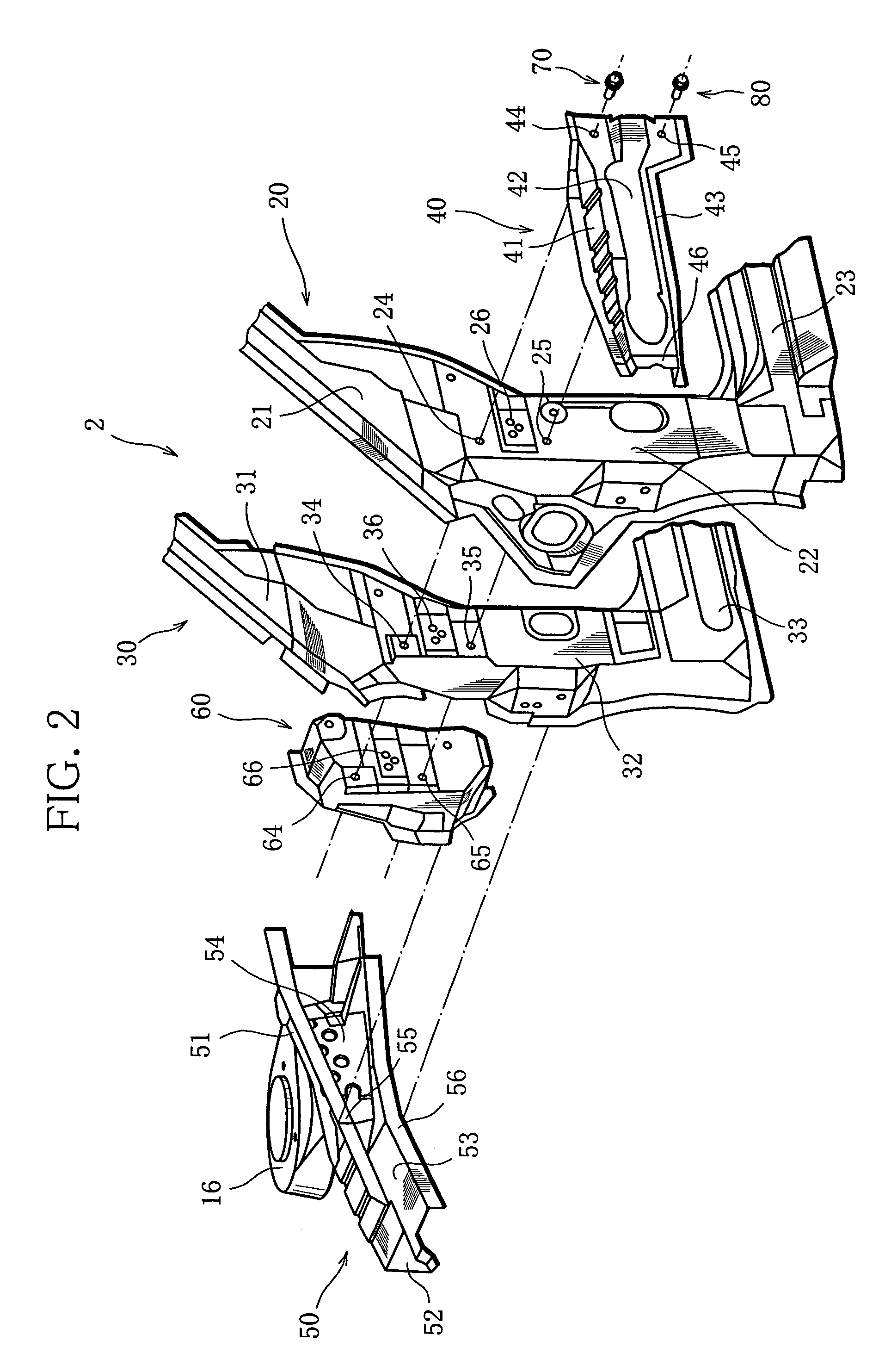
[0048]FIGS. 5 and 6 show a left-side vehicle body structure around an engine room of a sedan vehicle, which structure includes the vehicle body frame structure of this embodiment. A right-side vehicle structure (not shown) is symmetrical to the left-side vehicle structure with respect to the vehicle center.

[0049]As shown in FIG. 5, the vehicle body frame structure of this embodiment is basically the same as that of the first embodiment shown in FIG. 1 except in that it comprises a brace member which reinforces the connection between the front body and the side body. In FIGS. 5–8, elements corresponding to those shown in FIGS. 1–4 are each denoted by reference numeral equal to the sum of reference numeral in FIGS. 1–4 and 100.

[0050]The following is a brief explanation on the structure common to the first embodiment. In a front body 103 of a vehicle body 101, left and ...


PUM


Abstract

A vehicle body frame structure capable of realizing the connection to a side body in the form of structural connection. The vehicle body frame structure includes a side body whose skeleton is formed by a body panel that forms a side face of the vehicle body and a reinforcement member that is formed into a shape extending along the inside of the body panel and joined to the body panel, a front frame member that forms a front body disposed to form a shape extending from the side body to the front of the vehicle body, and an outer frame member joined to the front frame member from side of the vehicle body and secured to the reinforcement member by means of bolts extending through the body panel.

Description

CROSS-REFERENCE TO A RELATED APPLICATION[0001]This nonprovisional application claims priority under 35 U.S.C. §119(a) on Patent Application Nos. 2003-307455 and 2003-307456 both filed in Japan on Aug. 29, 2003, the entire contents of which are hereby incorporated by reference.BACKGROUND OF THE INVENTION[0002]1. Field of the Invention[0003]This invention relates to a vehicle body frame structure, and more particularly, to a vehicle body frame structure that provides an improved connection structure between a front body and a side body.[0004]2. Description of the Related Art[0005]In a vehicle body, various components such as an engine, front wheel suspensions, a radiator, and the like are generally mounted to a front body. Thus, the front body has various parts varying in rigidity. A side body, which is disposed on a rear side of the front body, is required to have a function of suppressing the vehicle body from being deformed in a height direction thereof.[0006]The connection between...

Claims


Application Information

Patent Timeline
Patent Type & Authority Patents(United States)
IPC IPC(8): B62D25/02B62D25/08B62D25/04
CPCB62D25/04B62D25/082
Inventor MIYOSHI, SHINSUKEYAKATA, TAKASHIYATABE, TAKAYUKIKIKUCHI, TAKASHIGOTO, KEISHISHIBATA, KOJI
Owner MITSUBISHI MOTORS CORP
Why Eureka
Try Eureka