Cargo barrier

a technology for preventing cargo and avoiding damage, applied in the direction of cargo supporting/securing components, transportation and packaging, railway components, etc., can solve the problems of increasing radial loading at the attachment points, affecting the design of the net, and the location of the attachments provided by the airframe manufacturer may not necessarily be in the best position for symmetrical and efficient net design, etc., to achieve the effect of reducing the undesirable longitudinal distension of the net, reducing the extension, and increasing the radial loading

Inactive Publication Date: 2006-11-28
AMSAFE BRIDPORT LTD
View PDF23 Cites 11 Cited by
  • Summary
  • Abstract
  • Description
  • Claims
  • Application Information

AI Technical Summary

Benefits of technology

[0011]The net may comprise materials that have a low extension at breaking point such as metallic cables or plastics fibre cables (such as aramid fibre cables). Such a barrier allows undesirable longitudina

Problems solved by technology

However, this type of design can often be compromised by restrictive radial load limits set by the airframe manufacturer and applied to the attachment points on the aircraft structure.
This problem is aggravated when the maximum permissible longitudinal distension of the net is low, as a net that has a lower distension at higher lo

Method used


Image

  • Cargo barrier
  • Cargo barrier
  • Cargo barrier

Examples


Embodiment Construction

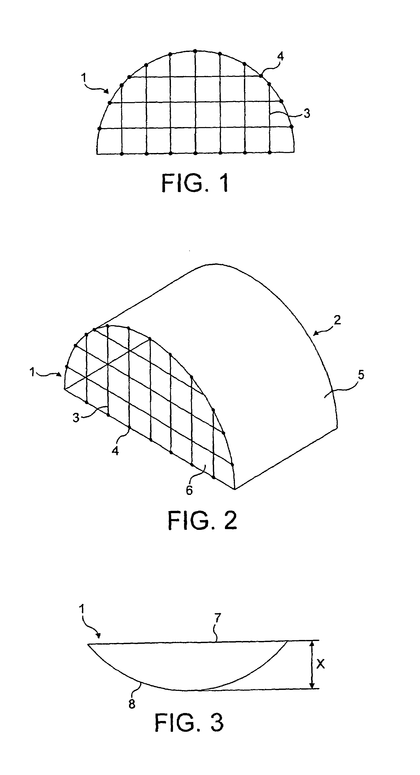
[0022]FIGS. 1 and 2 show a known net barrier 1 for restraining longitudinal movement of cargo within an upper deck cargo area of an aircraft 2, the barrier comprising a net 3 directly attached to attachment points 4 on the fuselage 5 of the aircraft 2 and floor 6 of the upper deck.

[0023]If longitudinal cargo movement occurs with this known net barrier, loading of the net barrier 1 results and the net barrier 1 distends from its normal position 7 to a longitudinally distended position 8 by a distance X, as shown in FIG. 3 This distension results in a force with a radial component being applied to the net fixing points.

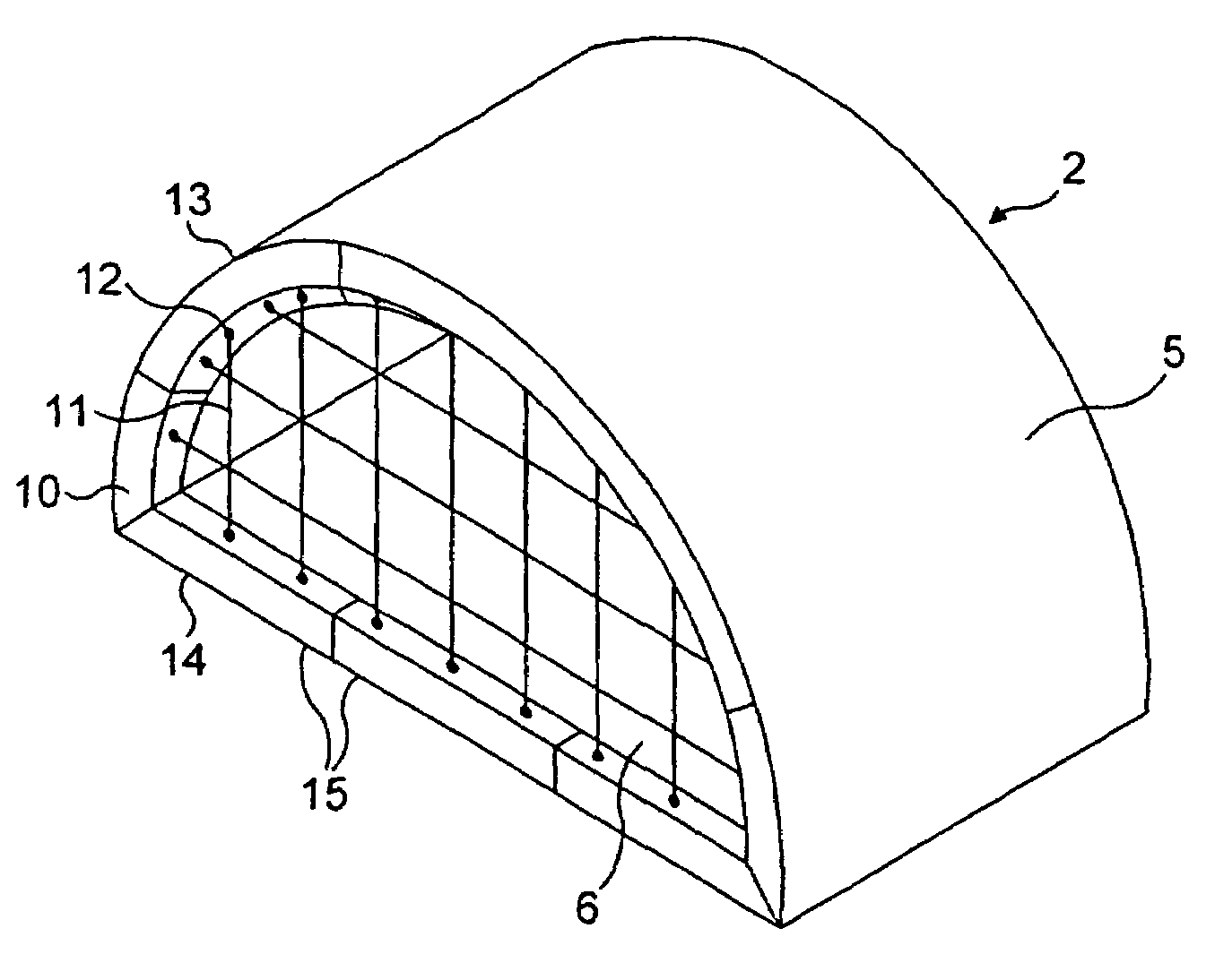
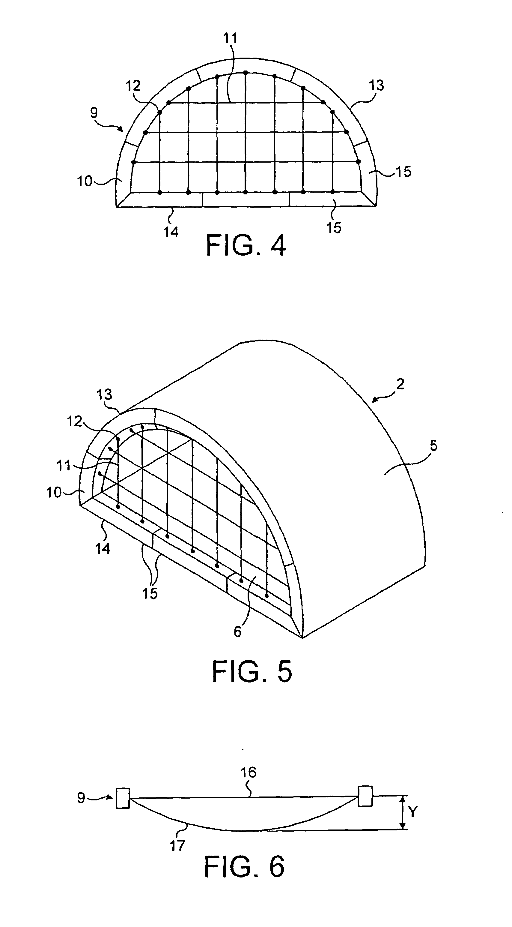
[0024]As shown in FIGS. 4 and 5, a cargo barrier 9 comprises a peripheral frame structure 10 made of rigid material and a cargo restraining net 11. The net 11 is attached to attachment points 12 on the frame structure 10, and the frame structure 10 is attached to attachment points (not shown) on the fuselage 5 of the aircraft 2 and floor 6 of the upper deck. In the draw...


PUM


Abstract

A cargo barrier (9) in or for installation in an aircraft (2), the barrier (9) comprising a peripheral frame structure (10) of rigid material and a cargo restraining net (11), the frame structure (10) being, in the aircraft (2), attached to attachment points on the interior structure of the aircraft and the net being attached to attachment points (12) on the frame structure (10). The frame structure (10) and net (11), in use, form a barrier across an interior space of the aircraft (2) in order to restrain longitudinal movement of cargo within the aircraft (2).

Description

BACKGROUNG OF THE INVENTION[0001]The present invention relates to a cargo barrier in or for installation in an aircraft.[0002]A conventional design of cargo barrier for the restraint of cargo on the main deck of a freighter or combi aircraft comprises a net attached to attachment points on the interior structure of the aircraft. However, this type of design can often be compromised by restrictive radial load limits set by the airframe manufacturer and applied to the attachment points on the aircraft structure. This problem is aggravated when the maximum permissible longitudinal distension of the net is low, as a net that has a lower distension at higher loads results in greater radial loading at the attachment points. In addition, the location of the attachments provided by the airframe manufacturer may not necessarily be in the best positions for a symmetrical and efficient net design.[0003]A common alternative to the use of a net barrier is the use of a rigid barrier, or bulkhead....

Claims


Application Information

Patent Timeline
IPC IPC(8): B61D45/00B64D9/00
CPCB64D9/00
Inventor ACKERMAN, DAVIDCARDEN, STEPHEN ROBERT
Owner AMSAFE BRIDPORT LTD
Why Eureka
Try Eureka