Rotation detecting apparatus

a detection apparatus and rotating technology, applied in the direction of acceleration measurement using interia forces, magnetic field measurement using permanent magnets, instruments, etc., can solve the problems of low design freedom of rotation detection apparatus, limited practical range for adjusting the deflection angle of magnetic vectors, and unavoidably increasing the total number of metal molds. , to achieve the effect of high sensing sensitivity and high degree of design freedom

Active Publication Date: 2006-11-28
DENSO CORP
View PDF4 Cites 14 Cited by
  • Summary
  • Abstract
  • Description
  • Claims
  • Application Information

AI Technical Summary

Benefits of technology

[0007]In view of the above-described problem, it is an object of the present invention to provide a rotation sensor having high sensing sensitivity and high degree of design freedom.
[0009]The above apparatus can control the deflection angle of the magnetic vector so that the detection sensitivity of the rotation is improved. Further, the deflection angle of the magnetic vector can be controlled by the shape of the bias magnet so that the degree of design freedom becomes larger.
[0012]The above apparatus can control the deflection angle of the magnetic vector so that the detection sensitivity of the rotation is improved. Further, the deflection angle of the magnetic vector can be controlled by the shape of the bias magnet so that the degree of design freedom becomes larger.
[0014]The above apparatus can control the deflection angle of the magnetic vector so that the detection sensitivity of the rotation is improved. Further, the deflection angle of the magnetic vector can be controlled by the shape of the bias magnet so that the degree of design freedom becomes larger.
[0016]The above apparatus can control the deflection angle of the magnetic vector so that the detection sensitivity of the rotation is improved. Further, the deflection angle of the magnetic vector can be controlled by the shape of the bias magnet so that the degree of design freedom becomes larger.

Problems solved by technology

That is, for instance, parts numbers as to these changed case members must be increased, and also, a total number of metal molds must be unavoidably increased which are required to mold these changed case members.
In an actual case, such an adjustment itself that the deflection angles of the magnetic vectors are adjusted only by changing the above-described M-to-M distance may cause some limitations.
That is, a freedom of designing as to the rotation detecting apparatus is low, and the range for adjusting the deflection angles of the magnetic vectors is restricted in the practical field.

Method used


Image

  • Rotation detecting apparatus
  • Rotation detecting apparatus
  • Rotation detecting apparatus

Examples


first embodiment

[0051](First Embodiment)

[0052]The inventors have preliminary studied about rotation detecting apparatus as a comparison of a first embodiment of the present invention. The apparatus is capable of detecting rotations by utilizing resistance value changes in the magnetic resistance elements. FIG. 17 indicates a flat-surface structure of a rotation detecting apparatus such as a crank angle sensor of an engine.

[0053]As shown in FIG. 17, in this rotation detecting apparatus, a sensor chip 11 has been arranged in such a manner that this sensor chip 11 is located opposite to a rotor “RT” which corresponds to an object to be detected. The sensor chip 11 has been equipped with a magnetic resistance element pair 1 which is constituted by two pieces of magnetic resistance elements MRE1 and MRE2; and also, another magnetic resistance element pair 2 which is constituted by two pieces of magnetic resistance elements MRE3 and MRE4. Then, the sensor chip 11 has been manufactured in an integrated ci...

second embodiment

[0103](Second Embodiment)

[0104]Prior to descriptions as to a second embodiment mode of a rotation detecting apparatus according to the present invention, a basic idea of the present invention will now be explained with reference to FIG. 19 to FIG. 21. It should be understood that for the sake of easy understandings, such a conventional rotation detecting apparatus which employs a biasing magnet is employed as an example, and a portion of this biasing magnet is indicated in an enlarging manner. In this biasing magnet, magnetic field strengths have been substantially uniformly set over an entire peripheral portion of the own biasing magnet. For the sake of convenience, the same reference numerals shown in the previous drawing of FIG. 17, or FIG. 18 will be employed as those for indicating the same, or similar structural elements indicated in FIG. 19 to FIG. 21.

[0105]FIG. 19 shows a perspective structure of a sensor chip 11 and a biasing magnet 13 in an enlarging manner, which constitu...

third embodiment

[0128](Third Embodiment)

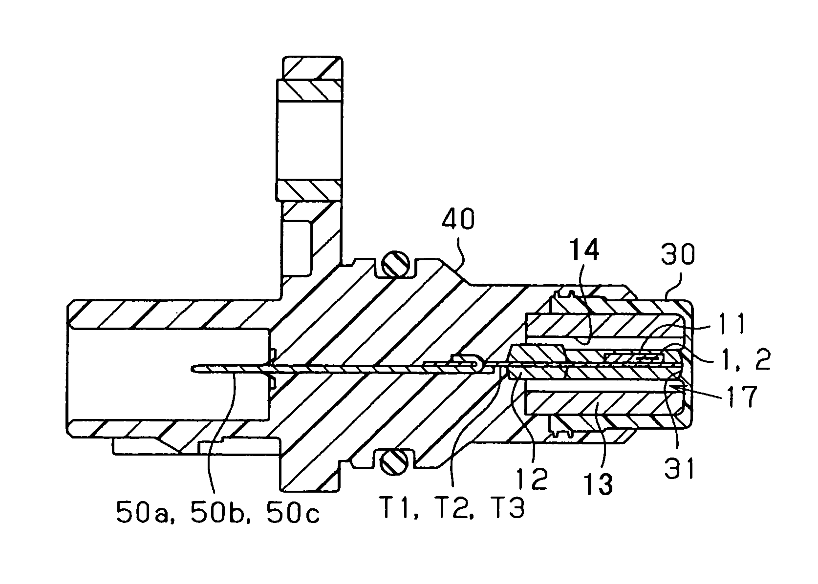
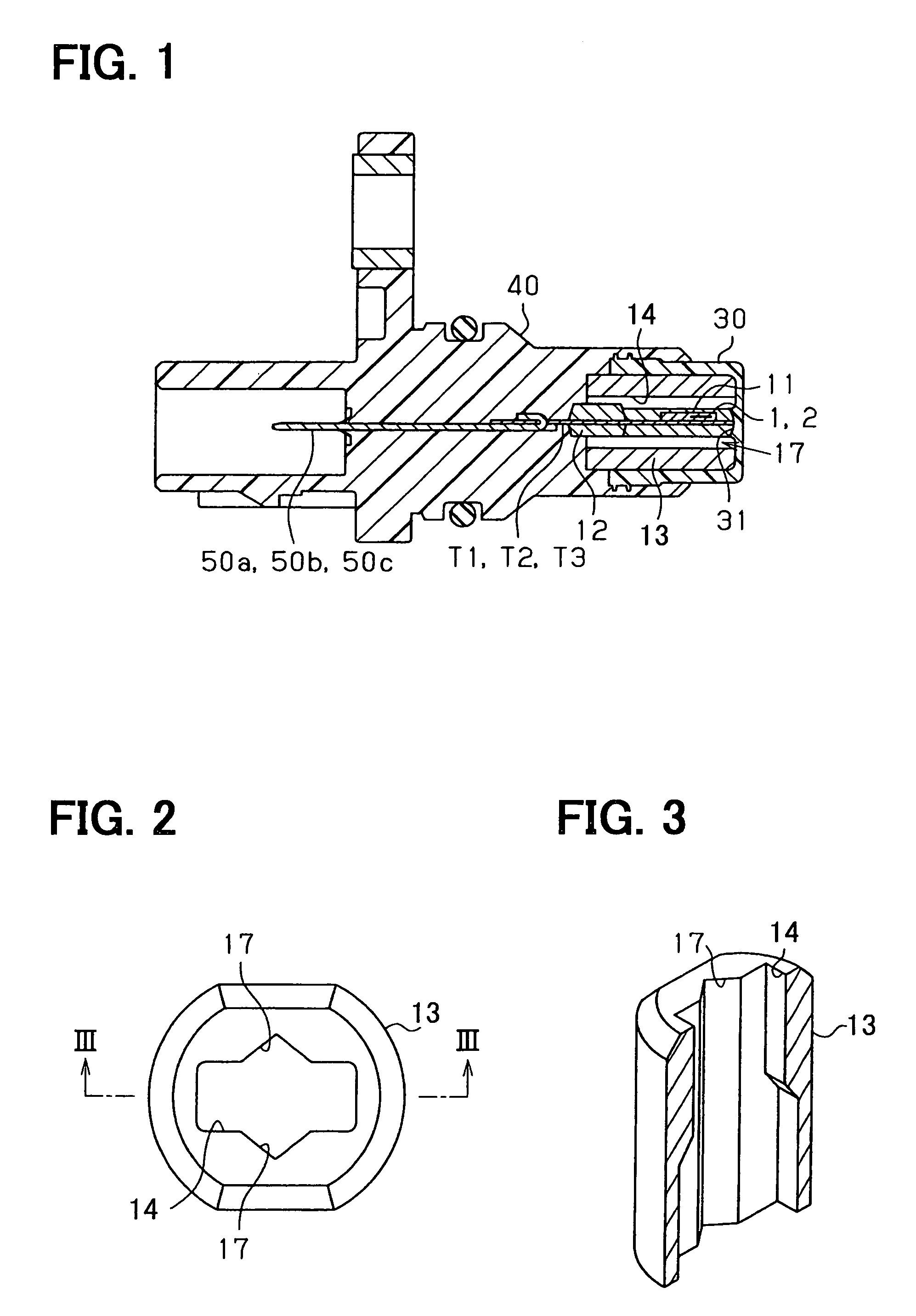
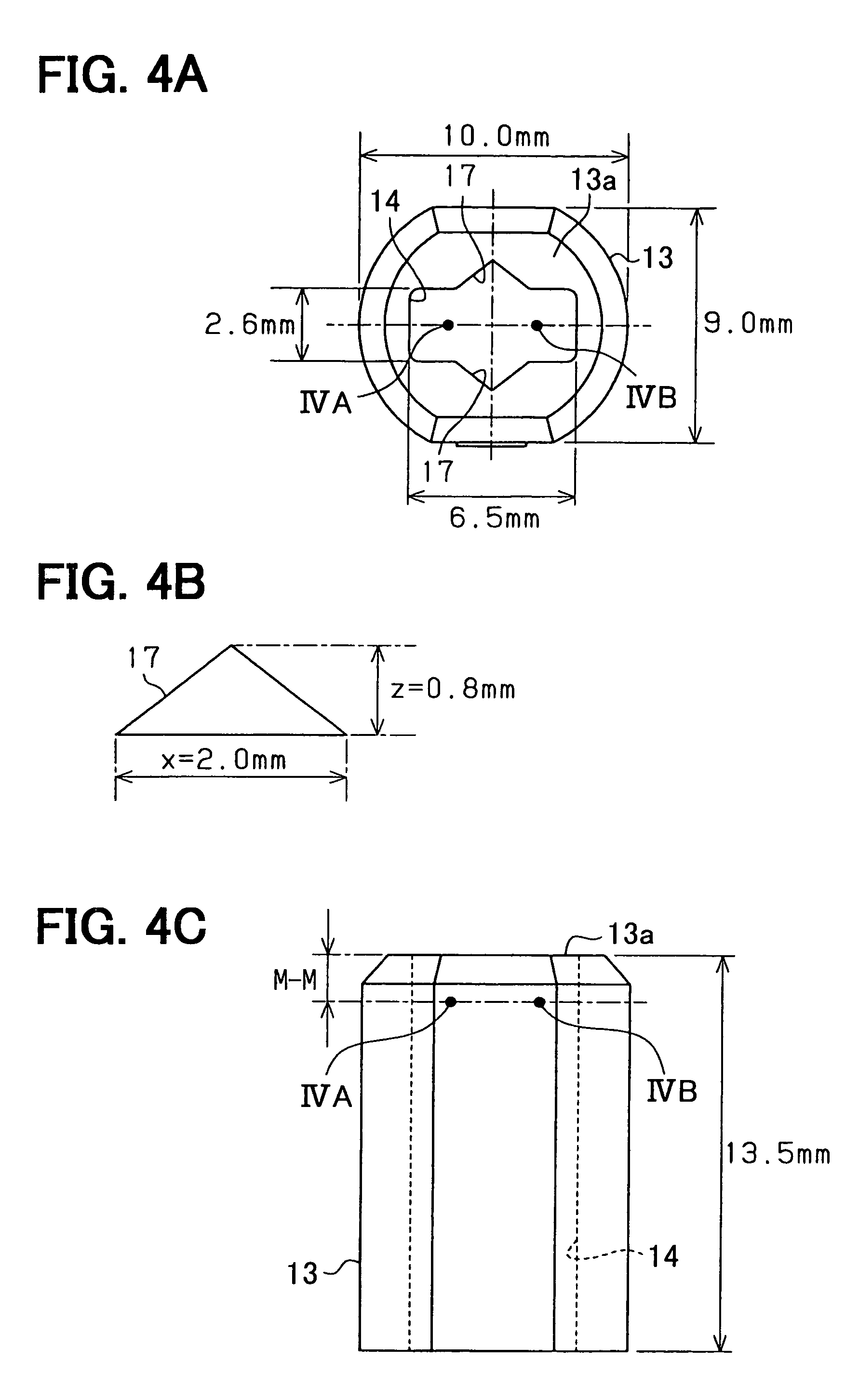
[0129]FIG. 29 shows a rotation detecting apparatus according to a third embodiment mode of the present invention, while the rotation detecting apparatus has been arranged based upon the above-described basic idea. Referring now to FIG. 29, an arrangement of the rotation detecting apparatus according to this third embodiment mode will be described in detail. It should be noted that since a structure as the rotation detecting apparatus is basically identical to the above-described structure of the conventional rotation detecting apparatus, the same reference numerals shown in this conventional rotation detecting apparatus will be employed as those for denoting structural elements having the same, or similar functions, and thus, detailed descriptions thereof are omitted.

[0130]FIG. 29 illustratively indicates conditions of magnetic fields which are generated from a biasing magnet 13 employed in the rotation detecting apparatus according to the first embodiment mo...


PUM


Abstract

Rotation detecting apparatus for detecting rotation of a magnetic rotor includes: a sensor chip having a magnetoresistive device; and a bias magnet. The magnetoresistive device is capable of detecting change of a magnetic vector near the sensor chip so that the rotation detecting apparatus detects the rotation of the magnetic rotor. The change of the magnetic vector is generated by the bias magnetic field and the rotation of the magnetic rotor. The bias magnet is disposed around the sensor chip so that a deflection angle of the magnetic vector is controllable.

Description

CROSS REFERENCE TO RELATED APPLICATIONS[0001]This application is based on Japanese Patent Applications No. 2004-196038 filed on Jul. 1, 2004, and No. 2004-327742 filed on Nov. 11, 2004, the disclosures of which are incorporated herein by reference.FIELD OF THE INVENTION[0002]The present invention relates to rotation detecting apparatus.BACKGROUND OF THE INVENTION[0003]A rotation detecting apparatus detects, for instance, revolutions of an engine mounted on a vehicle, and rotations of a rotator provided in a general-purpose machine. More specifically, the rotation detecting apparatus is capable of detecting rotation modes of the rotor by utilizing changes contained in resistance values of magnetic resistance elements.[0004]Conventionally, as the above-described rotation detecting apparatus capable of detecting the rotations by utilizing the resistance value changes in the magnetic resistance elements, for example, a rotation detecting apparatus described in Japanese Laid-open Patent ...

Claims


Application Information

Patent Timeline
Patent Type & Authority Patents(United States)
IPC IPC(8): G01B7/30G01P15/08G01P15/105G01R33/038G01R33/09
CPCG01D5/147G01R33/038G01R33/09
Inventor SUMIYA, KAZUYOSHIISHIO, SEIICHIRO
Owner DENSO CORP
Why Eureka
Try Eureka