
TCP receiver acceleration

a receiver and acceleration technology, applied in the field of network communication methods and devices, can solve the problems of no guarantee of uniqueness across different computers, software implementations of tcp receiver logic are limited by operating system performance constraints, and no longer the case, so as to accelerate the handling of tcp segments and minimize time expended

Active Publication Date: 2006-11-28
AVAGO TECH INT SALES PTE LTD
View PDF31 Cites 22 Cited by
  • Summary
  • Abstract
  • Description
  • Claims
  • Application Information

AI Technical Summary

Benefits of technology

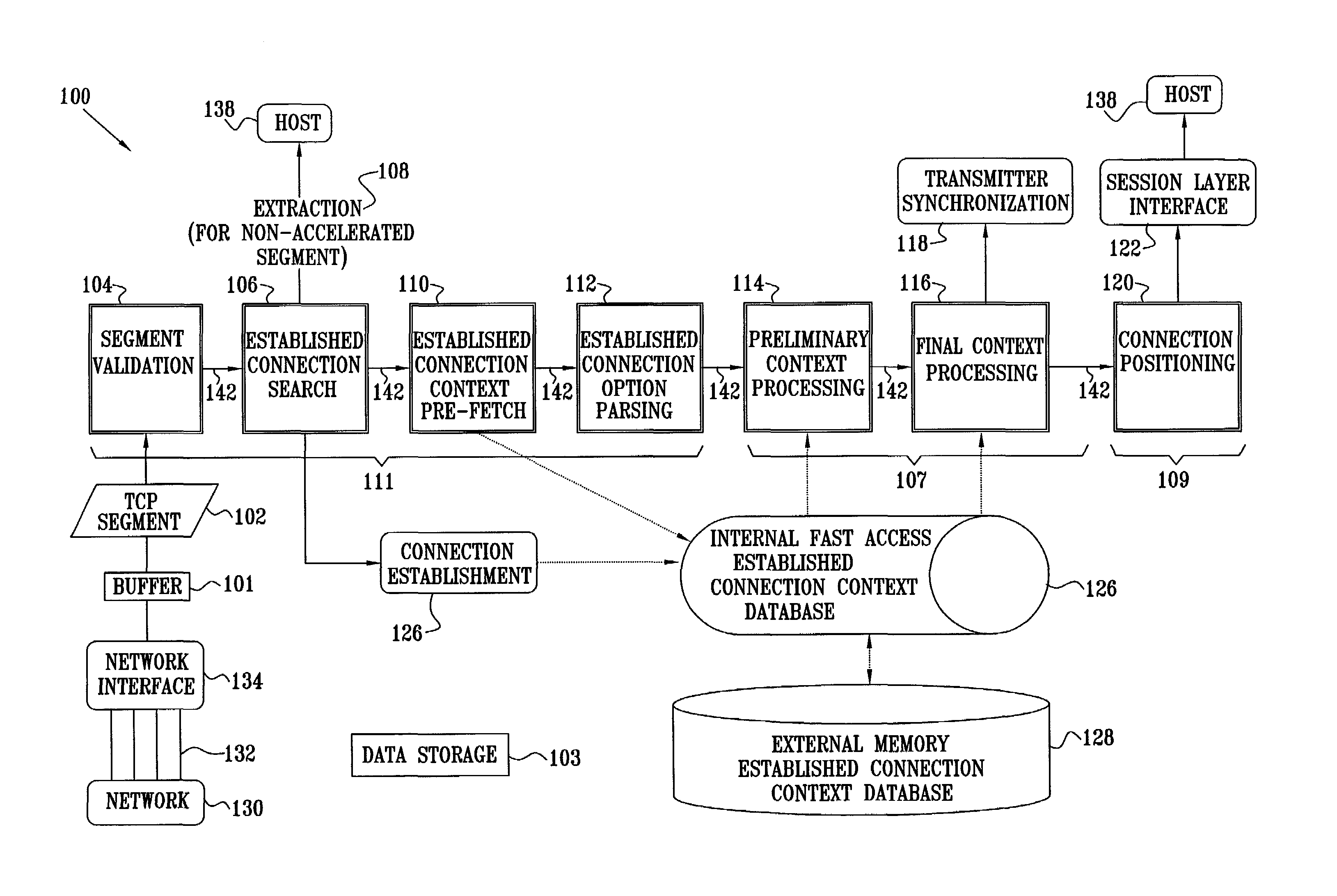
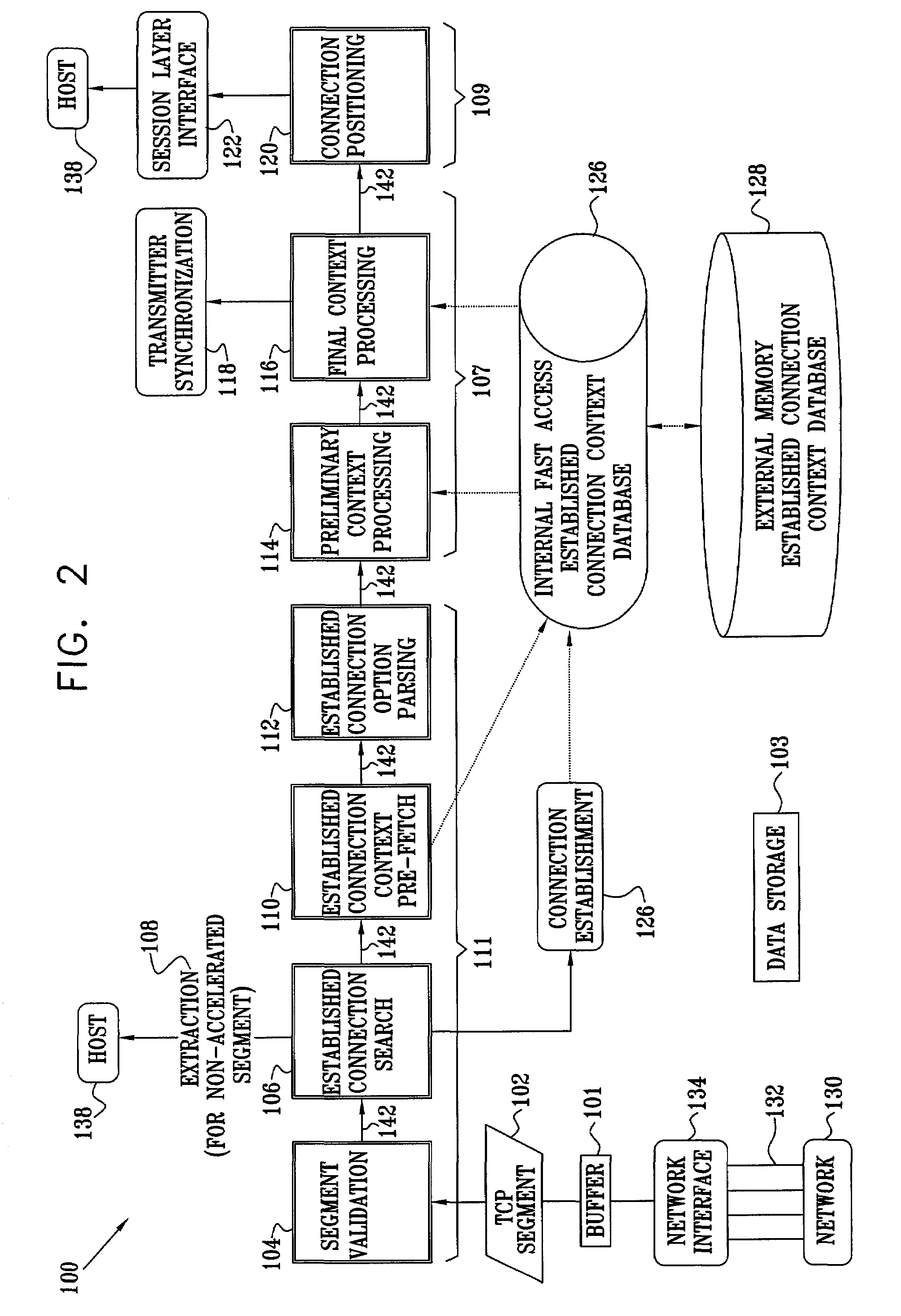
[0027]Optimal use of processor resources is facilitated, by partitioning the TCP receiver processing into phases implemented in modules using specific instruction-level optimization;
[0028]Modules containing autonomous subsets of operations are coupled together in a distributed pipeline architecture, maximizing parallel processing capabilities;
[0029]Information is transferred between modules using an efficient inter-module information forwarding mechanism, streamlining parameter passing by avoiding traditional data load / store overhead; and
[0030]A fast internal memory for connection context information, interfaced to an external memory containing a database of established connection control blocks is coupled to the modules in the pipeline so as to minimize time expended on searching and retrieving connection information, thereby further accelerating handling of the TCP segments.

Problems solved by technology

Port numbers are unique within a host computer, however, there is no guarantee of uniqueness across different computers.
However, notwithstanding this and numerous other improvements, software implementations of TCP receiver logic are limited by operating system performance constraints, as well as inefficiencies deriving from the serial nature of program execution in general-purpose microprocessors and associated overhead.
However, with the advent of network speeds in the Gbps and 10 Gbps range, this is no longer the case.

Method used


Image

  • TCP receiver acceleration
  • TCP receiver acceleration
  • TCP receiver acceleration

Examples


Embodiment Construction

[0094]Reference is now made to FIG. 2, which is a schematic block diagram depicting modules in a distributed pipeline 100 for hardware acceleration of TCP receiver processing, according to a preferred embodiment of the present invention. In the context of the present patent application and in the claims, the following definitions apply. The term “module” is defined as a hardware implementation of a stage of a TCP receiver pipeline. The term “subset” is defined as a short execution unit comprised within a module. The term “path” is defined as an ordered sequence of subsets defining a handling for a class of segments.

[0095]An efficient implementation of the TCP receiver processing requires a hardware-oriented approach to the classification and routing of the segments. As described in more detail below, such an approach comprises distributing the classification process among a plurality of modules, so as to achieve a successive refinement of the classification. The successively-refined...


PUM


Abstract

A transport protocol receiver for receiving a packet from a network, the packet having a header, payload, and connection context. The receiver includes an analysis engine, coupled to receive the packet from the network and adapted to parse and validate the header, locate the connection context, and generate a classification of the header. The receiver further includes a context processing engine, coupled to the analysis engine, and adapted to evaluate and update the connection context, responsive to the classification; and a data dispatch engine, coupled to the analysis engine and the context processing engine, and adapted to convey the payload to a destination, responsive to the connection context, such that the analysis engine, the context processing engine, and the data dispatch engine operate substantially asynchronously.

Description

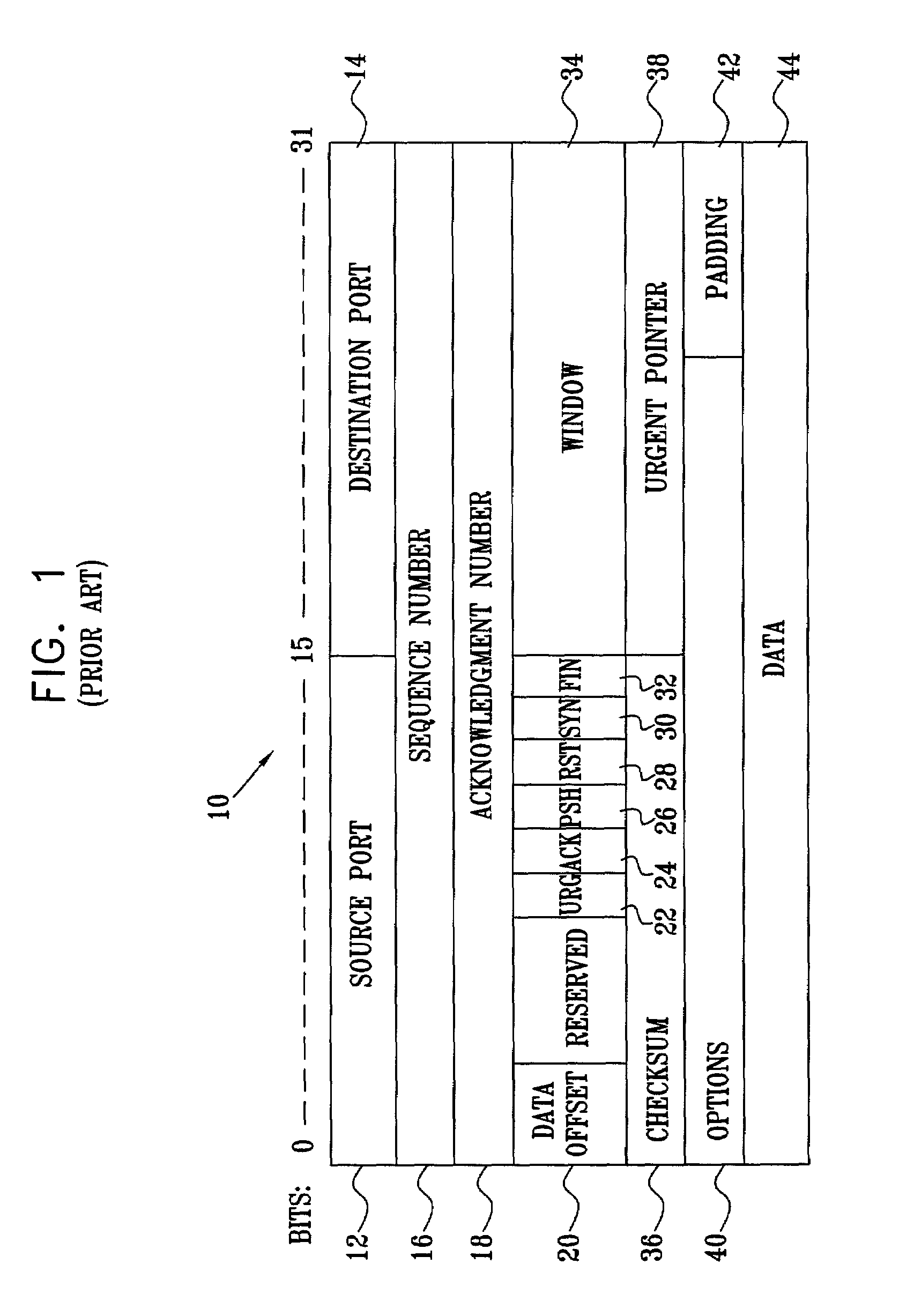
CROSS-REFERENCE TO RELATED APPLICATIONS[0001]This application claims the benefit of U.S. Provisional Patent Application 60 / 294,854 filed May 31 2001, which is assigned to the assignee of the present invention and which is incorporated herein by reference.FIELD OF THE INVENTION[0002]The present invention relates generally to methods and devices for network communications, and specifically to streamlining operation of reliable communication transport protocols.BACKGROUND OF THE INVENTION[0003]The Transmission Control Protocol / Internet Protocol (TCP / IP) suite is a widely-used transport protocol in digital packet networks. The TCP is described by Postel in RFC 793 of the U.S. Defense Advanced Research Projects Agency (DARPA), entitled “Transmission Control Protocol: DARPA Internet Program Protocol Specification” (1981), which is incorporated herein by reference. TCP is a connection-oriented, end-to-end, full-duplex protocol, which provides for reliable inter-process communication betwee...

Claims


Application Information

Patent Timeline
IPC IPC(8): H04L12/28G06FG06Q40/00H04L12/56H04L29/06
CPCG06Q40/04H04L69/16H04L69/161
Inventor GRINFELD, RON
Owner AVAGO TECH INT SALES PTE LTD
Learn More