Method and apparatus for pavement cross-slope measurement

a technology of cross-slope measurement and equipment, which is applied in the direction of distance measurement, instruments, ways, etc., can solve the problems of high cost, high labor intensity, and difficulty in achieving the effect of high accuracy

Inactive Publication Date: 2006-11-28
MEKEMSON JAMES R +1
View PDF8 Cites 4 Cited by
  • Summary
  • Abstract
  • Description
  • Claims
  • Application Information

AI Technical Summary

Benefits of technology

[0003]A need exists for a method and apparatus for accurately measuring pavement cross-slope that eliminates the lane closing requirement, reduces the risk to the crew performing the cross-slope measurement, is performed more quickly, and is less costly to perform.SUMMARY OF THE INVENTION
[0006]The present invention integrates lasers, a ring-laser gyroscope (RLG), and a distance measuring instrument (DMI). One primary distinction from existing cross-slope measurement apparatus is that existing systems use less real time accurate mechanical or fiber optic (FOG) gyroscopes. The RLG provides a higher level of accuracy with respect to the roll angle (cross-slope) measurement of the gyroscope.
[0009]The present invention reduces preconstruction, construction, and post-construction survey costs, reduces safety concerns, provides data in a shorter time period, and provides data for quantity estimates.

Problems solved by technology

Existing methods are very time consuming and require closing the lanes for which measurement of the cross-slope is desired.
Closing lanes on a heavily traveled road presents an element of danger to the crews taking the cross-slope measurements, as well as being an expensive task.
Additionally, the existing methods for collecting cross-slope measurements are time consuming, thereby leading to traffic problems for the long time that a stretch of roadway is closed to traffic.

Method used


Image

  • Method and apparatus for pavement cross-slope measurement
  • Method and apparatus for pavement cross-slope measurement
  • Method and apparatus for pavement cross-slope measurement

Examples


Embodiment Construction

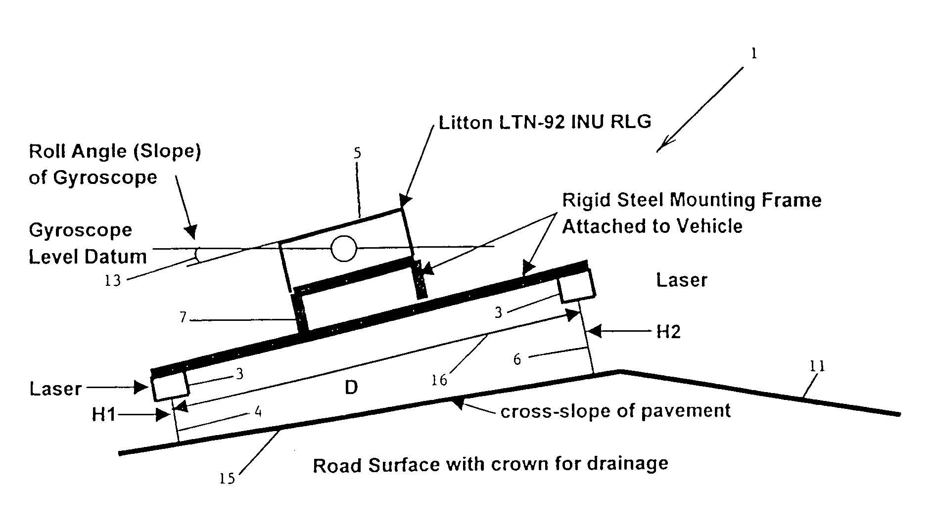
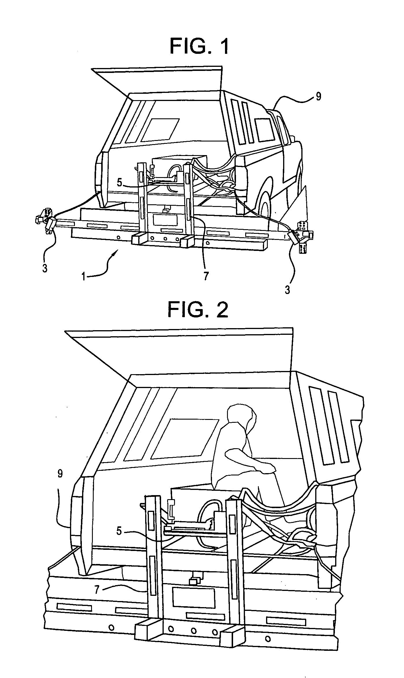
[0023]The present invention 1 is an apparatus and method of measuring pavement cross-slope at highway speeds, as shown in FIGS. 1, 2 and 11. The apparatus for obtaining cross-slope measurements uses lasers 3 and a gyroscope 5. Lasers 3 provide the measurement of vehicle 9 roll with respect to the pavement 11. The ring-laser gyroscope (RLG) 5 provides the measurement of vehicle 9 roll with respect to a level datum, shown as angle 13 in FIG. 11. From these two measurements, the cross slope (roll angle) 15 of the pavement may be determined.

[0024]The apparatus for measuring pavement cross-slope may be mounted in a vehicle 9. The apparatus is capable of making accurate measurements from a vehicle as it travels over pavement at speeds up to 60 miles per hour. The hardware and software system is vehicle based for the accurate measurement of pavement cross slope and may be used at highway speeds of up to 60 mph.

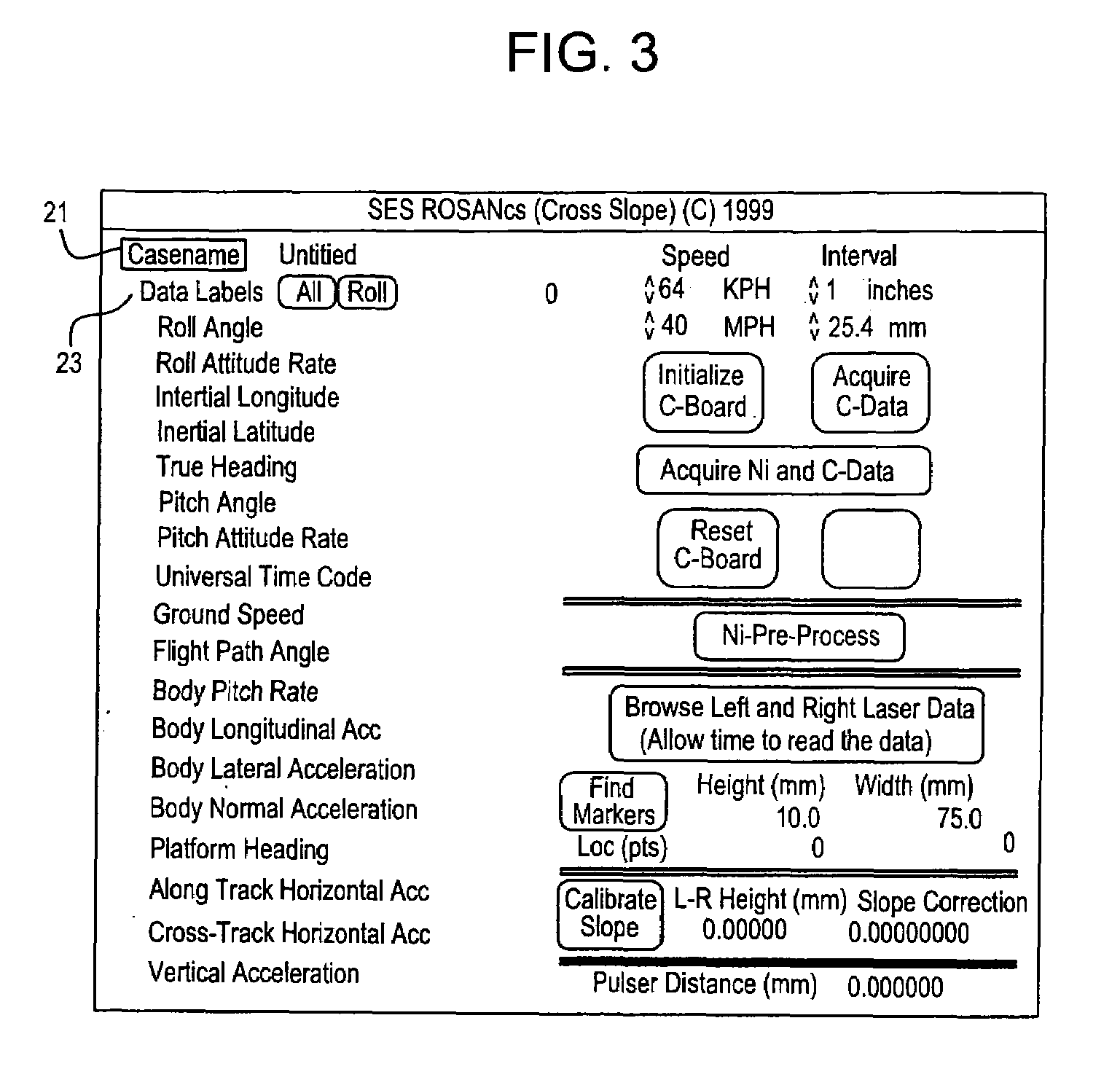
[0025]The present invention integrates lasers 3, a ring-laser gyroscope (RLG) 5,...


PUM


Abstract

Pavement cross-slope is measured at highway speeds by mounting a ring-laser gyroscope on a vehicle and measuring deviation of the transverse slope of the vehicle. Precise laser distance measuring devices are mounted transversely with respect to the vehicle at significantly distant points to measure vehicle roll by measuring displacement of the laser distance measuring units from the pavement. The difference between at rest measurements of the laser distance measuring devices, the dynamic measurements produced by those devices and the relation of the dynamic measurement to the distance between the measurements provides the exact value of vehicle roll with respect to the pavement. That exact value of vehicle roll is compared with the ring gyro angular measurement to produce a precise measurement of pavement slope. A positional device is mounted on the vehicle for determining the position of the vehicle on the roadway. A computer is mounted on the vehicle and a recording device is mounted on the vehicle to record the precise slope of the roadway at the precise position on the pavement being measured.

Description

BACKGROUND OF THE INVENTION[0001]This application claims the benefit of U.S. Provisional Application No. 60 / 187,031 filed Mar. 6, 2000.[0002]Pavement cross-slope is an important safety factor in pavement drainage and vehicle cornering. Existing methods are very time consuming and require closing the lanes for which measurement of the cross-slope is desired. Closing lanes on a heavily traveled road presents an element of danger to the crews taking the cross-slope measurements, as well as being an expensive task. Additionally, the existing methods for collecting cross-slope measurements are time consuming, thereby leading to traffic problems for the long time that a stretch of roadway is closed to traffic.[0003]A need exists for a method and apparatus for accurately measuring pavement cross-slope that eliminates the lane closing requirement, reduces the risk to the crew performing the cross-slope measurement, is performed more quickly, and is less costly to perform.SUMMARY OF THE INVE...

Claims


Application Information

Patent Timeline
Patent Type & Authority Patents(United States)
IPC IPC(8): G05D1/00G01C21/32G05D3/00G01C7/04
CPCG01C7/04
Inventor MEKEMSON, JAMES R.GAGARIN, NICOLAS
Owner MEKEMSON JAMES R
Why Eureka
Try Eureka