Model train controller interface device

a controller and interface device technology, applied in the direction of vehicle position/course/altitude control, process and machine control, instruments, etc., can solve the problems of ineffective control of cab-1 hand held remote, inability of tmcc to control dcs, and limited interfa

Inactive Publication Date: 2006-11-28
NEISER ROBERT C
View PDF5 Cites 20 Cited by
  • Summary
  • Abstract
  • Description
  • Claims
  • Application Information

AI Technical Summary

Benefits of technology

[0023]A third embodiment, similar to the interface cable of the second embodiment, connects directly to the TIU and is designed to eliminate the need of the prior art TIU / TMCC serial cable.

Problems solved by technology

Both the Lionel TMCC and the MTH TIU have serial data ports that once connected allow for limited interoperability between the two competing systems.
However, as noted, the interface is limited.
DCS can control TMCC but TMCC cannot control DCS.
Therefore, the use of the TMCC-TIU cable precludes the use of the TMCC ASC devices, and for all intents and purposes, renders the CAB-1 hand held remote ineffective to control TMCC accessories through TMCC ASC devices.

Method used


Image

  • Model train controller interface device
  • Model train controller interface device
  • Model train controller interface device

Examples


first embodiment

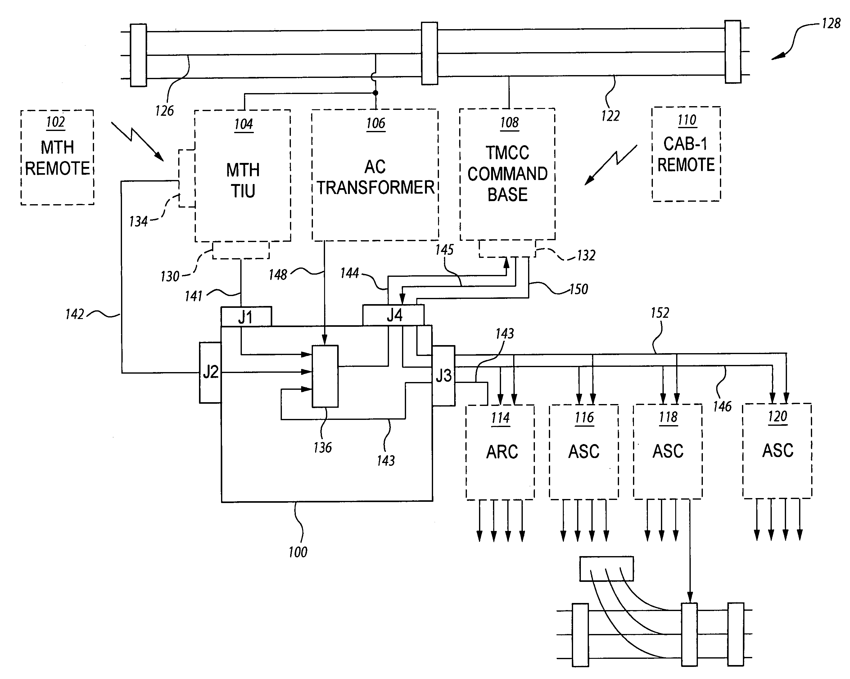
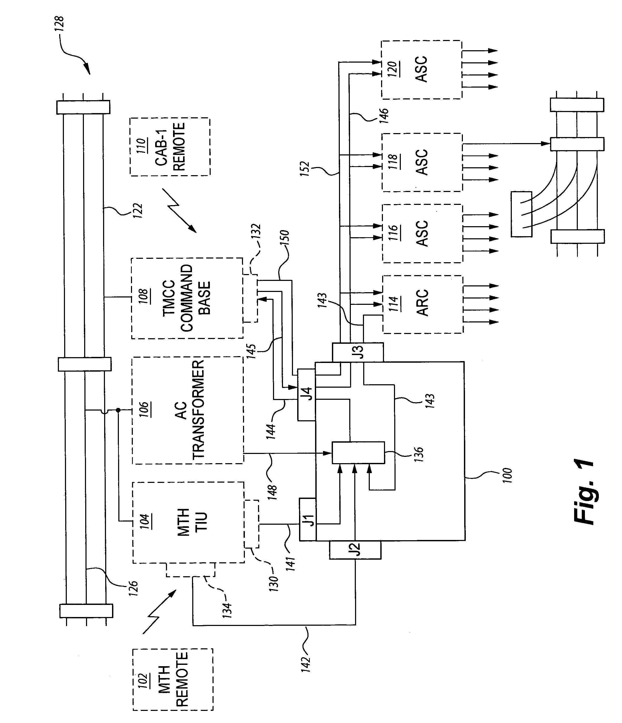
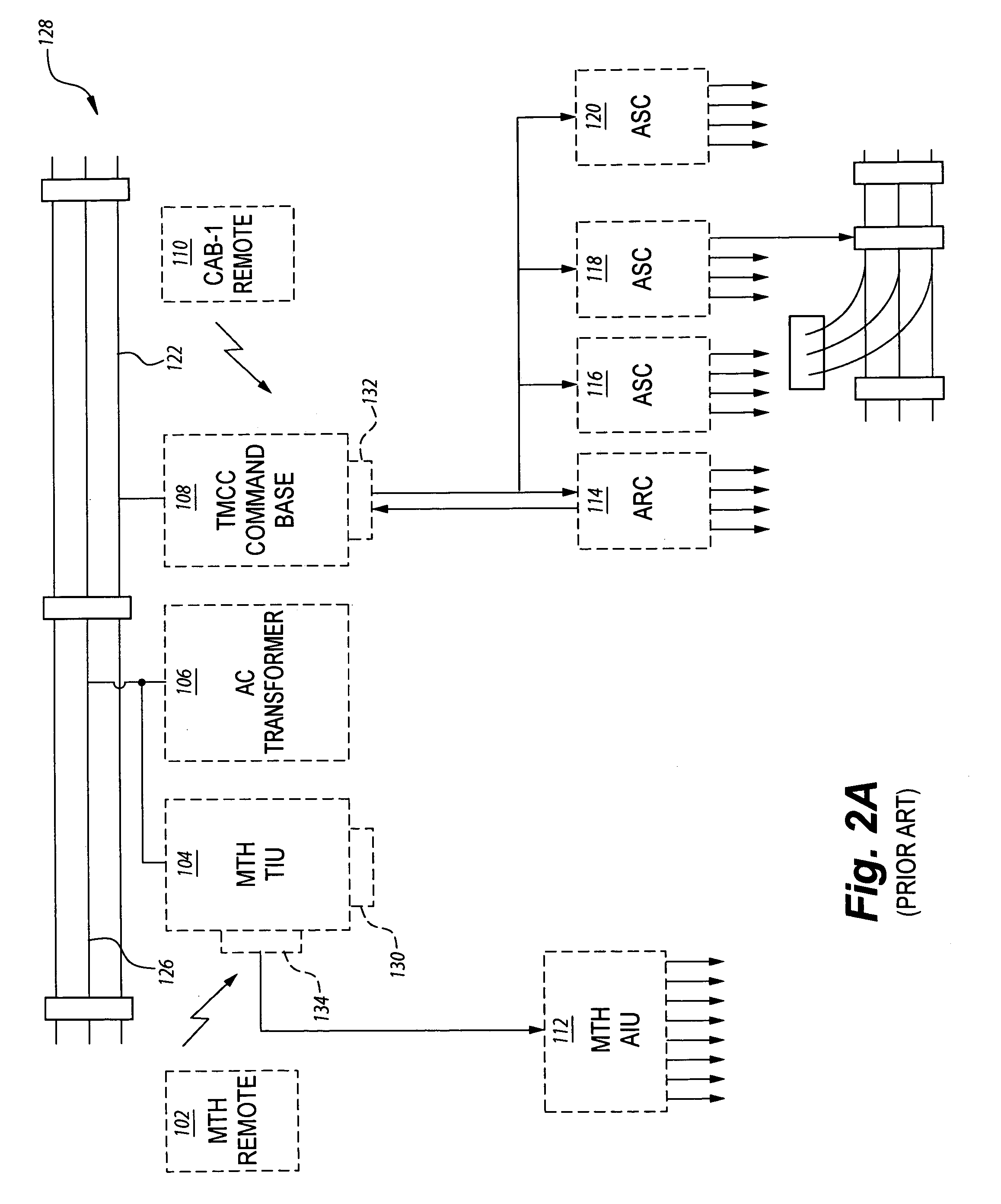
[0035]FIG. 1 represents a block diagram of the present invention 100 incorporated in a model train layout having both TMCC and Mike's Train House (MTH) model train components. FIG. 2A represents prior art and illustrates a train layout in which the MTH model train components provide no commands to TMCC equipped components. In other words, the MTH handheld wireless device 102 can control only MTH engines and devices connected to the Accessory Interface unit (AIU) 112. Likewise, the CAB-1 remote 110 can control only TMCC engines and TMCC controllers, such as Accessory Switch Controllers (ASC) 116–120 and the Action Recorder Controller (ARC) 114.

[0036]Still illustrating the prior art, FIG. 2B represents an alternate track layout in which the MTH TIU 104 and the TMCC command base 108 are interconnected by a TIU / TMCC serial cable 206 having female and male 9-pin connectors 202, 204 connected between TIU 104 port 130 and TMCC base command unit 108 port 132 respectively. Implementing the T...

second embodiment

[0056]FIG. 4 illustrates the present invention in which a specially designed interface cable 400 retains the ability of the CAB-1 110 remote to command TMCC equipped switch and accessory device controllers 116–120 while permitting the MTH DCS remote 102 to command TMCC equipped engines.

[0057]Interface cable 400 comprises a cable 402 having at least two electrical conductors connected between two commercially available 9-pin “D” shell connectors 404, 406, one connector 406 is a 9-pin male connector and the other a 9-pin female connector 404. The interface cable 400 is similar to a commercially available “null modem” cable in that pin 2 of one connector is wired to pin 3 of the connector at the other end. Signal ground is transmitted though pin 5 on both connectors. Although the TMCC does not presently send commands to the TIU and therefore would not require a transmit lead from the TMCC to the TIU, this lead is made available for future use.

[0058]FIG. 5 illustrates the interconnectio...

embodiment 400

[0060]Still referring to FIGS. 6–7, interface cable 600 is similar to the cable interface disclosed as embodiment 400, in that pigtail 414 and conductors 408–412 extend from pins 2,3 and 5 of connector 606 and are connected to device controllers 114–120.


PUM


Abstract

The model train controller interface device provides a user with the capability of operating model train engine, switch and accessories of one manufacturer with the handheld wireless device of a second manufacturer. Inserted between the command base units and controller devices of different model train manufacturers, the interface device allows the wireless remote of one train system to operate components of the other train system without loss of functionality by either model train system.

Description

BACKGROUND OF THE INVENTION[0001]1. Field of the Invention[0002]The present invention relates to control systems for model trains, and particularly to devices that interface between control systems of different model train manufacturers, allowing one vendor's control unit to operate components of a competing manufacturer.[0003]2. Description of the Related Art[0004]Model train control systems have, as basic building blocks, a set of interconnected sections of train track, electric switches between different sections of the train track, a variety of electrically controlled devices, and finally, at least one electric train engine.[0005]Standard O-gauge electrical train operation is characterized by an AC track signal, wherein the AC signal is switchably offset by a DC signal used to enable various train accessories such as the horn / whistle function. The AC track signal energizes the electric motor of the train engine, with the DC offset enabling a train engine relay unit to activate t...

Claims


Application Information

Patent Timeline
Patent Type & Authority Patents(United States)
IPC IPC(8): A63H19/24G06F7/00
CPCA63H19/24
Inventor NEISER, ROBERT C.
Owner NEISER ROBERT C
Why Eureka
Try Eureka