Automated power management system for a network of computers

a technology of automatic power management and network computers, applied in the field of automatic power management system for network computers, can solve the problems of large amount of electrical power, large heat generation, and large consumption of power, and achieve the effects of reducing the demand for processing abilities of the system, less power consumption, and minimizing or minimizing consumption

Active Publication Date: 2006-11-28
HEWLETT-PACKARD ENTERPRISE DEV LP
View PDF6 Cites 82 Cited by
  • Summary
  • Abstract
  • Description
  • Claims
  • Application Information

AI Technical Summary

Benefits of technology

[0010]The problems noted above are solved in large part by a computer system comprising a plurality of computing entities and includes automatic power management logic that automatically transitions the system to a state which uses an amount of power commensurate with the processing demands for the system. For example, if the processing demands are reduced, the power management logic transitions the system to a state in which less power is consumed. The determination as to when this transition should occur is based on determining when demand for the processing abilities of the system is reduced. Once the decision has been made to transition to a reduced power state, the system's power management logic makes this transition in such a way to preferably minimize or at least reduce the performance impact on the system.

Problems solved by technology

Computers, of course, require electrical power to operate and, as a result, generate heat.
Networks of computers may require very substantial amounts of electrical power and which may cause a great deal of heat to be generated.
The electrical power required to power computers is, of course, not free of charge and, at times, may carry a very substantial cost.
The heat generated, particularly by networks of computers, may also be very substantial and, if not removed from the system, may damage the computers.
There is an additional cost associated with the cost of the electrical power required for the cooling systems necessary to remove the heat from the computers.
Although helpful in managing power consumption on an individual computer basis, this type of methodology may not be the most efficient technique to manage power in a network of computers.

Method used


Image

  • Automated power management system for a network of computers
  • Automated power management system for a network of computers
  • Automated power management system for a network of computers

Examples


Embodiment Construction

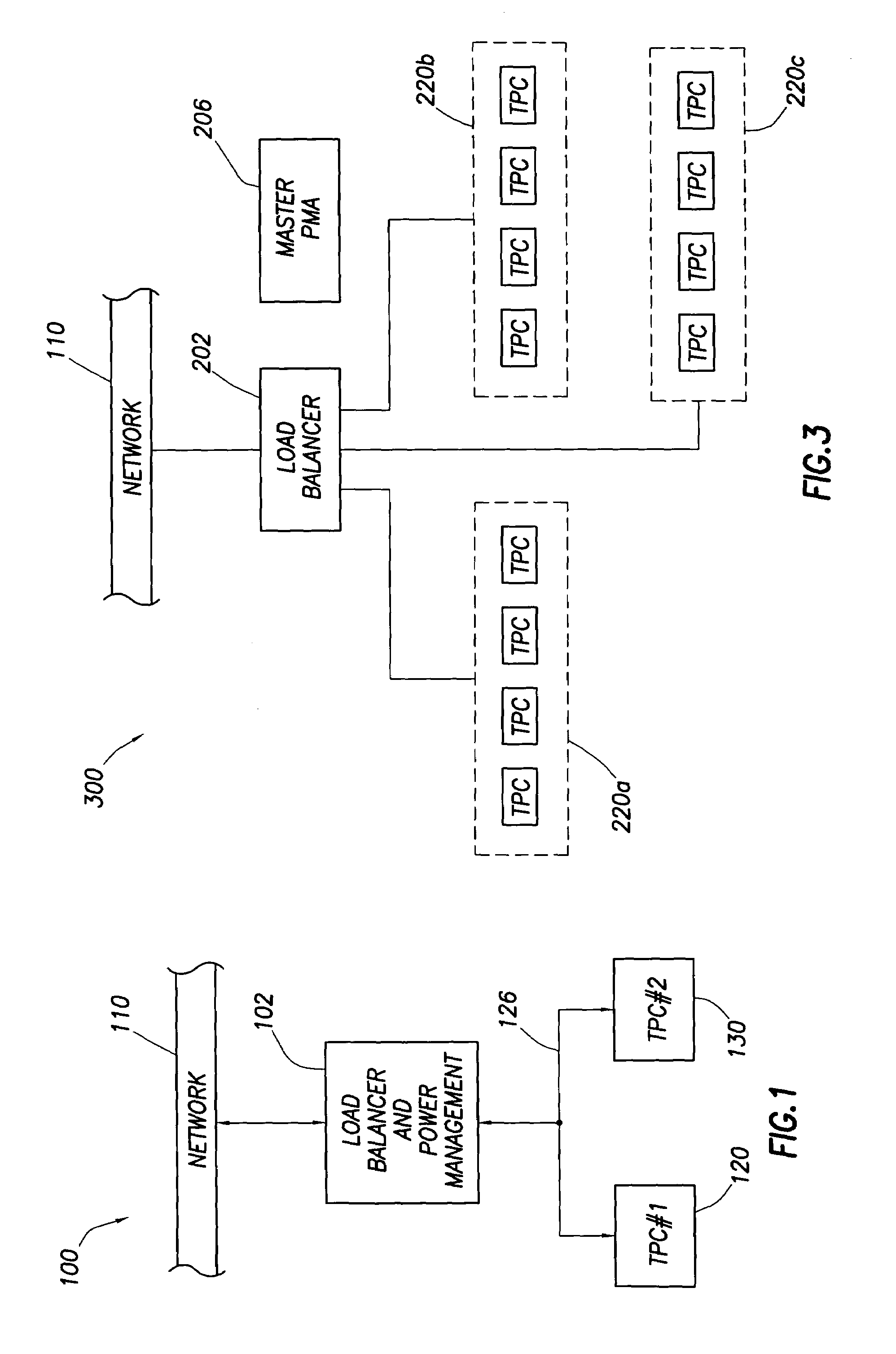
[0019]Referring now to FIG. 1, computer system 100, constructed in accordance with a preferred embodiment of the invention, comprises a load balancer and power management unit 102 coupled to two transaction processing computers (TPCs) 120 and 130. One or more than two TPCs can be included as desired. The load balancer and power management unit 102 may itself be implemented in the form of software, hardware or both on a computer or may be logic implemented in one or both of the TPCs 120, 130. Load balancer and power management unit 102 couples to a network 110 and also couples to TPCs 120, 130 preferably via a separate network 126. Network 110 may be represent any suitable type of network available to system 100 for receiving transactions for processing such as the Internet or any local or wide area networks. Each of the TPCs 120, 130 preferably are implemented as computers (e.g., servers) that execute off-the-shelf or custom software.

[0020]Computer system 100 can be set up to perfor...


PUM


Abstract

A computer system comprising a plurality of computing entities includes automatic power management logic that automatically transitions the system to a state in which less power is consumed when appropriate. The determination as to when this transition should occur is based on determining when demand for the processing abilities of the system are reduced. Once the decision has been made to transition to a reduced power state, the system's power management logic makes this transition in such a way to preferably minimize or at least reduce the performance impact on the system. Also, rather than altering the power state of one of the computing entities in the system, the entity can be deployed as part of another computing system.

Description

CROSS-REFERENCE TO RELATED APPLICATIONS[0001]Not applicable.STATEMENT REGARDING FEDERALLY SPONSORED RESEARCH OR DEVELOPMENT[0002]Not applicable.BACKGROUND OF THE INVENTION[0003]1. Field of the Invention[0004]The present invention relates generally to power management in a system comprising a plurality of computers. More particularly, the present invention relates to changing the power state of one or more computers in the system based on a change in demand for the processing capability of the system or in accordance with criteria specified by a user.[0005]2. Background of the Invention[0006]As is well known, a computer can execute a software application to perform virtually any desired function. As is also known, processing capability can be increased by networking together more than one computer. Each computer in the network then can be assigned one or more tasks to perform. By having a plurality of computers working in concert with each computer performing a portion of the overall...

Claims


Application Information

Patent Timeline
Patent Type & Authority Patents(United States)
IPC IPC(8): G06F1/26G06F15/173G06F1/32
CPCG06F1/3203G06F1/3209
Inventor POTTER, MARK R.BUSKE, THOMAS L.CAGLE, JOHN M.HEMPHILL, JOHN M.
Owner HEWLETT-PACKARD ENTERPRISE DEV LP
Why Eureka
Try Eureka