Rotary engine

a rotary engine and piston technology, applied in the direction of liquid fuel engines, machines/engines, rotary piston liquid engines, etc., can solve the problems of incomplete combustion, fuel loss, difficulty in providing an oil seal between the rotary member and the inner wall of the cylindrical housing, etc., and achieve the effect of large power

Inactive Publication Date: 2006-12-05
KIM DONG HYUN
View PDF33 Cites 15 Cited by
  • Summary
  • Abstract
  • Description
  • Claims
  • Application Information

AI Technical Summary

Benefits of technology

[0007]Therefore, the present invention has been made in view of the above problems, and it is an object of the present invention to provide a rotary engine that is capable of preventing leakage of oil or pressure, completely discharging exhaust gas, and performing explosion strokes at the rear of a partitioned exhaust chamber, whereby large power can be obtained.

Problems solved by technology

Consequently, the rotary member is rotated while being kept in whole contact with the inner wall of the cylindrical housing, whereby it is very difficult to provide an oil seal between the rotary member and the inner wall of the cylindrical housing.
Even if such an oil seal is provided between the rotary member and the inner wall of the cylindrical housing, at least some of the lubricant inevitably flows into the operating chambers when the rotary member passes by the lubricating section of the housing since an intake / exhaust port formed at each of the operating chambers is exposed with the result that incomplete combustion is caused due to the inflow of the lubricant.
Also, pressure leaks through the oil seal when high pressure is generated in the operating chambers during the compression stroke, expansion stroke, and exhaust stroke of the operating chambers, which leads to loss of fuel.
Furthermore, combustion in the rotary engine is not properly accomplished due to lack of the fuel.
As a result, high expansion pressure is not obtainable for the supplied amount of the fuel.
Moreover, the above-described rotary engine is not provided with means for discharging the exhaust gas left after the combustion in the rotary engine.
Consequently, large power cannot be obtained by means of the conventional rotary engine.

Method used


Image

  • Rotary engine
  • Rotary engine
  • Rotary engine

Examples


Embodiment Construction

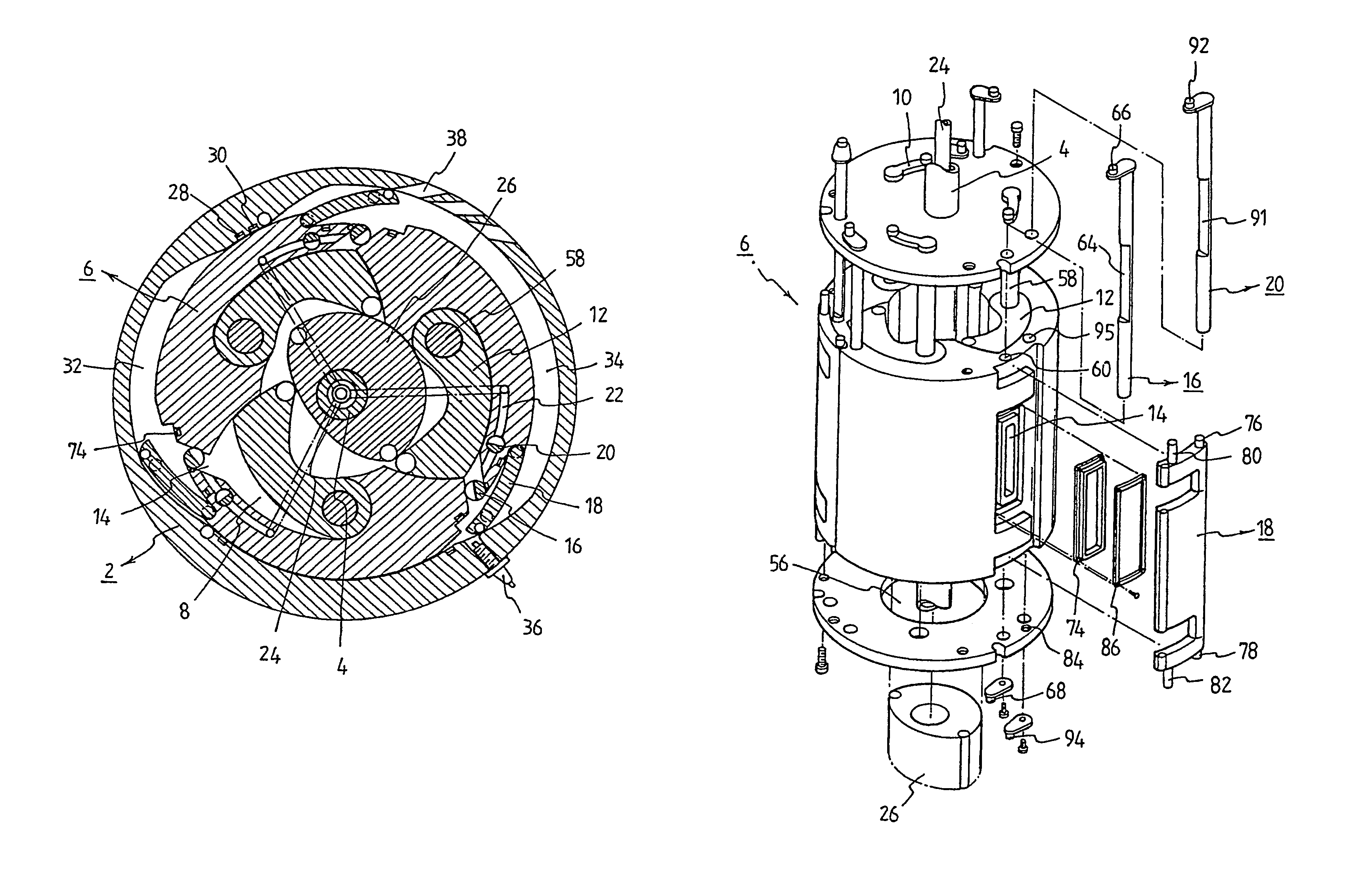
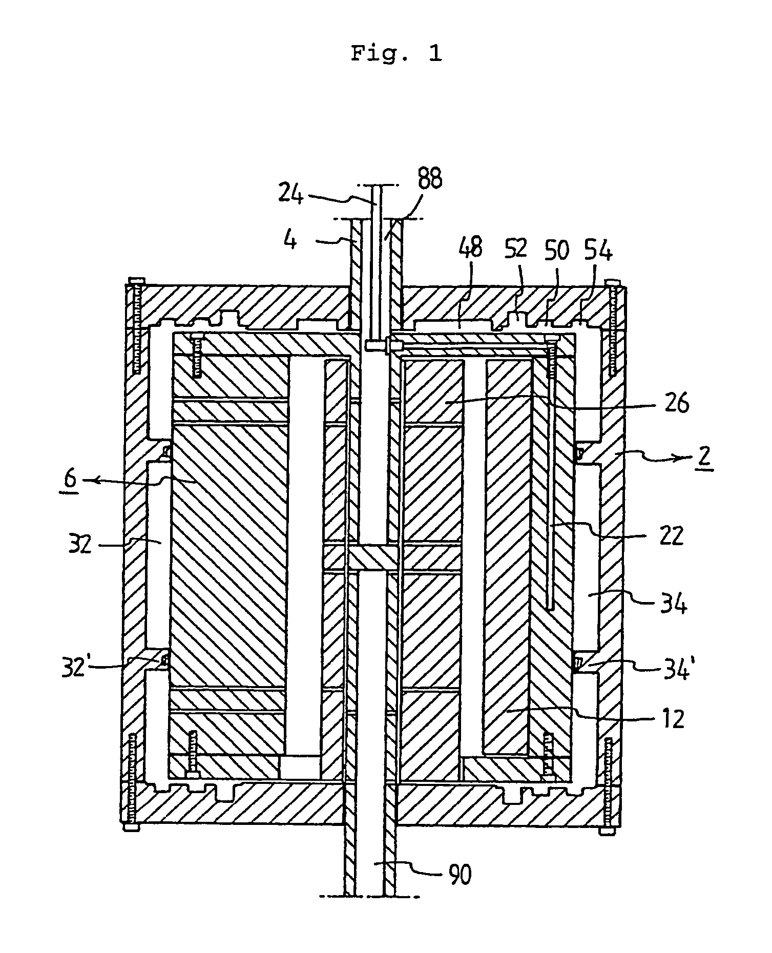
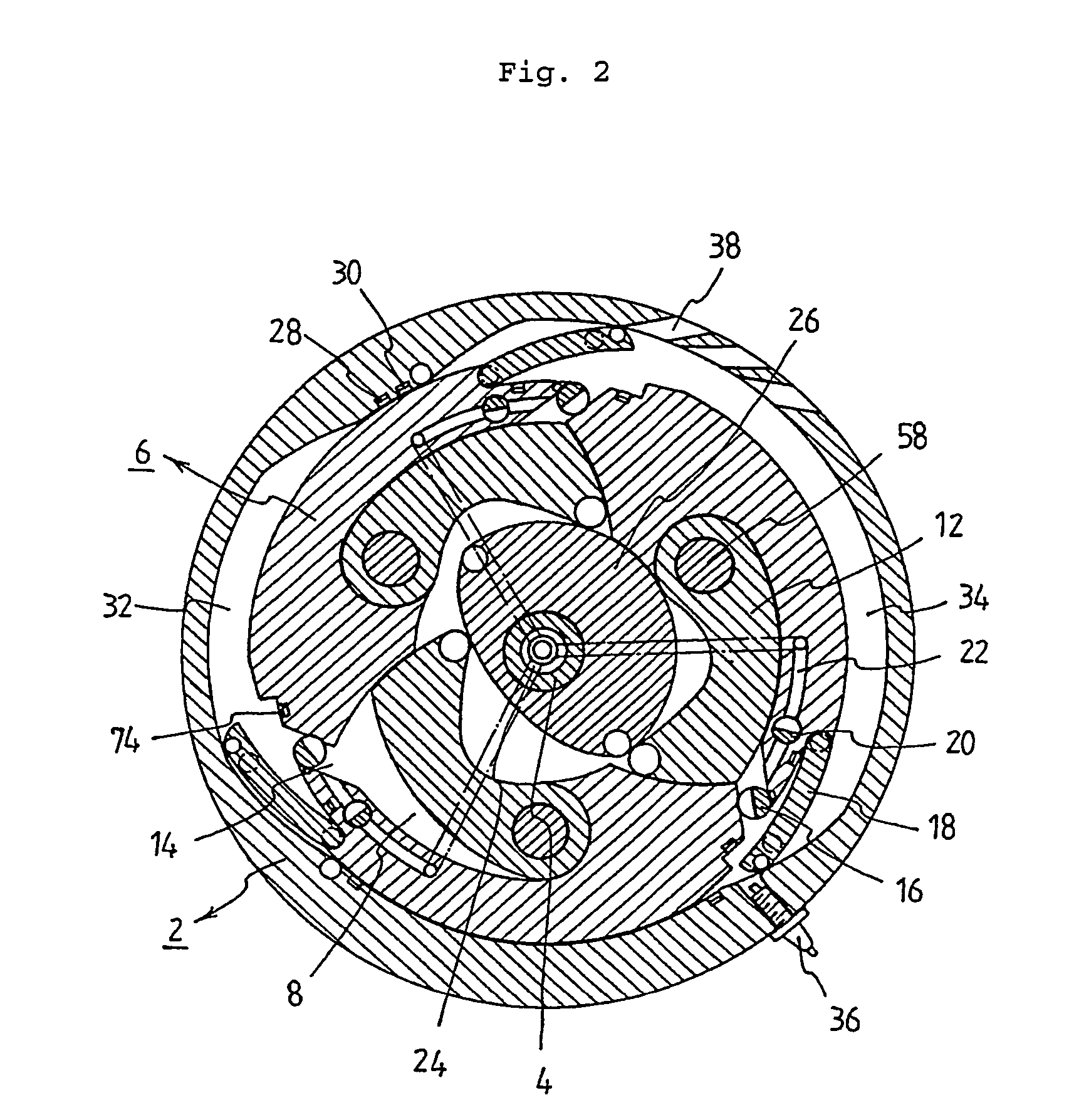
[0018]FIGS. 1 and 2 respectively show, in section, a rotary engine according to a first preferred embodiment of the present invention. As shown in FIGS. 1 and 2, the rotary engine of the present invention includes a rotary member 6 disposed in a cylindrical housing 2 in such a manner that the rotary member 6 is rotated along with a rotating shaft 4. The rotary member 6 is provided with a plurality of operating chambers 8, in which pistons 12 are disposed, respectively. The pistons 12 are guided by means of guiding pieces 10, respectively. Each of the operating chambers 8 is provided with an intake / exhaust port 14, at which a shutoff valve 16 and a shutoff plate 18 are disposed. In each of the operating chambers 8 is formed an air-supplying channel 22, which is opened / closed by means of another shutoff valve 20 mounted in the air-supplying channel 22. To each of the operating chambers 8 is connected an air-supplying conduit 24 through the air-supplying channel 22. At the center of th...


PUM


Abstract

A rotary engine includes pistons disposed in operating chambers of a rotary member. The pistons are guided by guiding pieces engaged in a guiding groove formed at a housing so that the operating chambers are expanded. Each of the operating chambers includes an intake / exhaust port, which is opened or closed by a shutoff valve and a shutoff plate guided along guiding grooves formed at the housing. An exhaust chamber is caved in the housing so that an explosion stroke is carried out at the rear part of the exhaust chamber, whereby a rotating force is obtained. Compressed air is supplied into the operating chambers through air-supplying channels, which are opened or closed by shutoff valves, so that gas left in the operating chambers is forcibly discharged. Consequently, introduction of lubricant through the intake / exhaust ports or leakage of pressure is prevented, and large power is obtained.

Description

TECHNICAL FIELD[0001]The present invention relates to an internal combustion engine, and more particularly to a rotary engine.Background Art[0002]Rotary engines are disclosed in PCT / KR02 / 00921, which has been filed in the name of the applicant of the present application, EP 103,985, and FR 1,255,205.[0003]In the rotary engine disclosed in each of the above patent documents, a rotary member is rotated about a rotating shaft in a cylindrical housing. When the rotary member is rotated, pistons disposed in operating chambers of the rotary member are slidably moved along the outer circumference of an elliptical guiding member disposed in the center of the rotary member so that the operating chambers are compressed and expanded by means of the pistons, respectively.[0004]Consequently, the rotary member is rotated while being kept in whole contact with the inner wall of the cylindrical housing, whereby it is very difficult to provide an oil seal between the rotary member and the inner wall...

Claims


Application Information

Patent Timeline
Patent Type & Authority Patents(United States)
IPC IPC(8): F02B53/00F02B57/00F01C1/00F02B59/00F04C18/00F01C1/40F02B53/02
CPCF01C1/40F02B53/02Y02T10/17Y02T10/12
Inventor KIM, DONG-HYUN
Owner KIM DONG HYUN
Why Eureka
Try Eureka