Coil arrangements

a coil and arrangement technology, applied in the field of coil arrangements, can solve the problems of local charge redistribution and broad-band electrical interference, and achieve the effects of minimizing the likelihood of partial discharg

Inactive Publication Date: 2006-12-05
TESLA ENG
View PDF10 Cites 7 Cited by
  • Summary
  • Abstract
  • Description
  • Claims
  • Application Information

AI Technical Summary

Benefits of technology

[0012]Positioning the shield coils so as to be electrically adjacent a virtual earth of the circuit is advantageous in minimizing the potential differences within the shield coil assembly, thereby minimizing the likelihood of partial discharge in the shield coils. Furthermore, mutual inductance between the drive coils and the shield coils acts to at least partially cancel self inductance of the shield coils.
[0013]The drive coils may be comprised of at least one group of drive coils including at least two respective drive coils connected together in series, wherein the coils are spatially arranged such that, in use, the potential differences between adjacent parts thereof are minimised, thereby minimising partial discharge therebetween.
[0014]According to another aspect of this invention there is provided a drive coil arrangement for use in Magnetic Resonance Imaging and Spectroscopy apparatus, the drive coil arrangement including at least one group of drive coils including at least two respective drive coils connected together in series, wherein the coils are spatially arranged such that, in use, the potential differences between adjacent parts thereof are minimised, thereby minimising partial discharge therebetween.

Problems solved by technology

However, if a potential difference above a certain threshold exists between spatially adjacent resin-impregnated drive coils, local charge redistribution can occur within microscopic voids and inhomogeneities in the resin.
This phenomenon is termed “partial discharge” and can create broad-band electrical interference that is deleterious to the sensitive radio frequency detection systems used in MRIS.

Method used


Image

  • Coil arrangements
  • Coil arrangements
  • Coil arrangements

Examples


Embodiment Construction

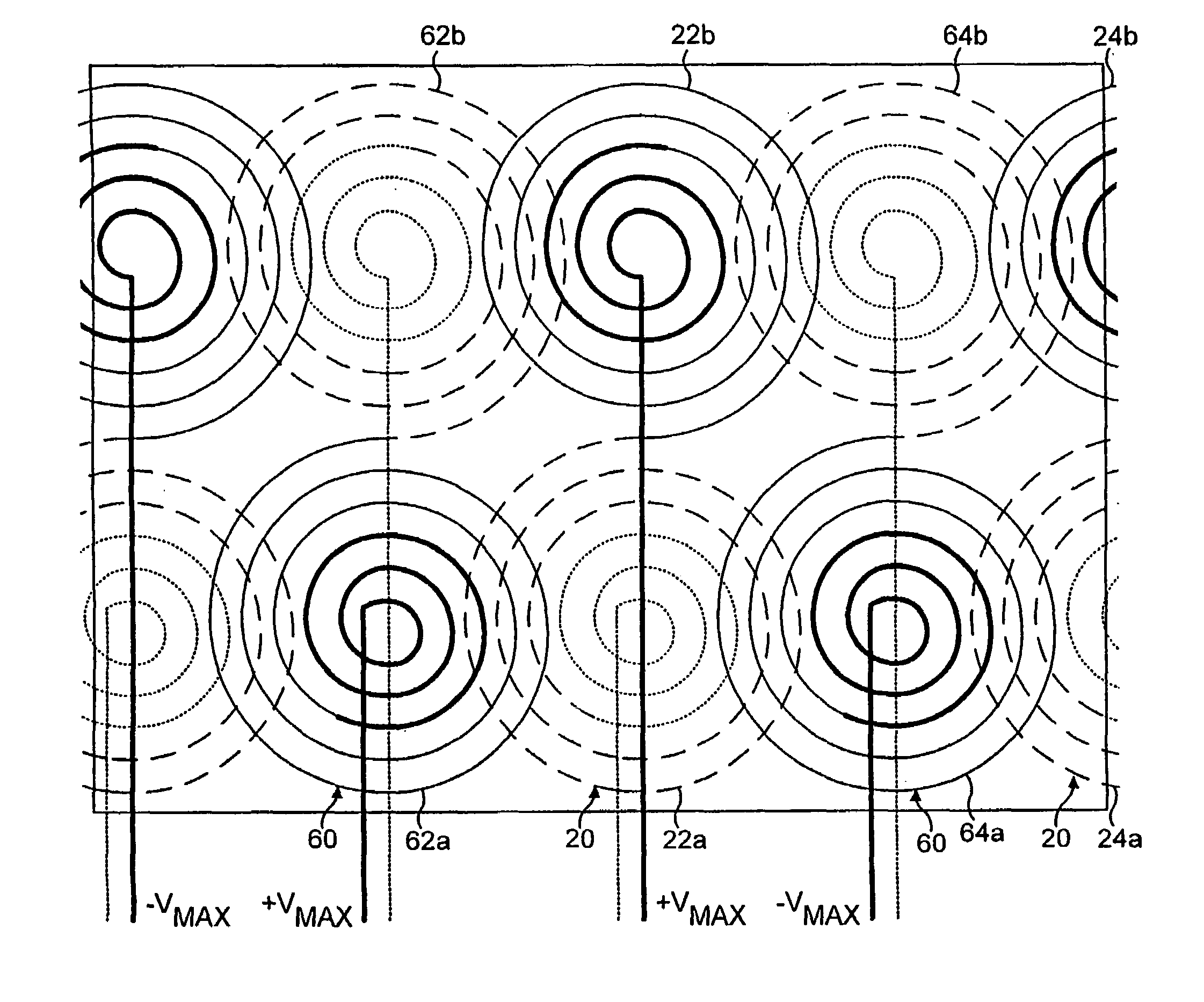
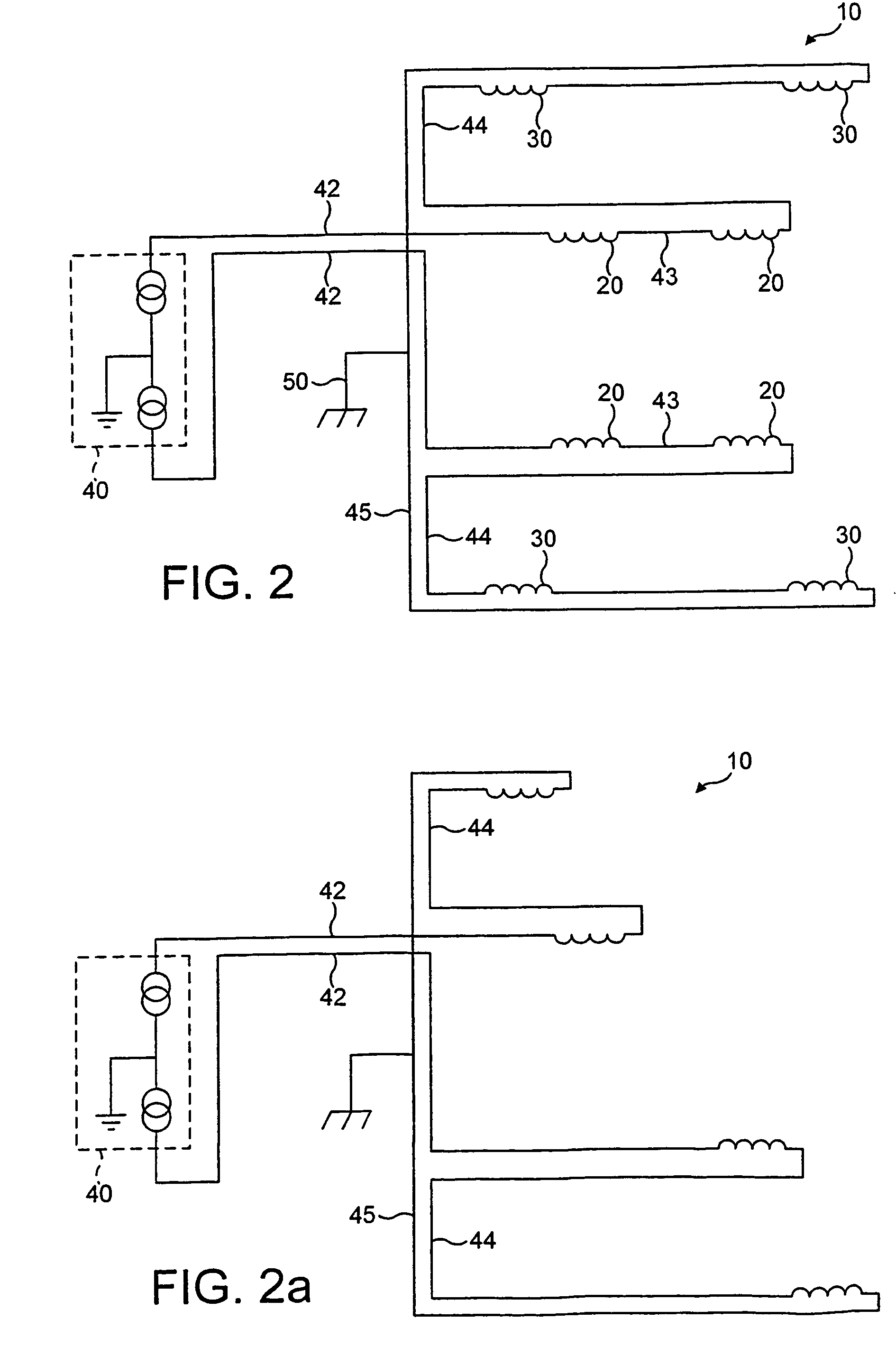
[0031]FIG. 2 shows, in schematic form, apparatus 10 for use in MRIS. The apparatus 10 includes drive coils 20, shield coils 30 and a power supply unit (PSU) 40. The drive coils are Y drive coils. It should be noted, however, that for the purposes of the description with reference to FIG. 2, the drive coils 20 may be X, Y or Z drive coils, the principle described with reference to FIG. 1 being of general application to all drive coils. The shield coils 30 shown in FIG. 2 are those that seek to shield the drive coils 20 of FIG. 2.

[0032]Some features of the drive coils 20 and the shield coils 30 are conventional. The drive coils 20 are comprised of four, spirally-wound coils 20 positioned on the outside surface of a cylinder (not shown). The drive coils 20 are arranged in two pairs, for example a top pair and a bottom pair, each pair being diametrically opposite the other pair. The shield coils 30 are arranged outside and around the drive coils 20 and are also comprised of four, spiral...


PUM


Abstract

Apparatus (10) for use in MRIS includes a coil arrangement having drive coils (20), shield coils (30) and a power supply unit (PSU) (40). The drive coils (20) and the shield coils (30) are connected in series to the PSU (40) to form a circuit. The shield coils (30) are connected between a first and second length of the drive coils (20) so as to straddle a virtual earth of the circuit. This is advantageous in minimising potential differences within the shield coil (30) assembly and thereby in minimising partial discharge therewithin. Partial discharge between adjacent parts of the drive coils (20) is minimised by spatially arranging those coils (20) such that parts thereof that are at a high electrical potential are spatially adjacent parts thereof that are simultaneously at a potential of the same polarity of at a low electrical potential of either polarity.

Description

[0001]This application is the US national phase of international application PCT / GB03 / 02448 filed 9 Jun. 2003 which designated the U.S. and claims benefit of UK 0213131.6, dated Jun. 7, 2002, the entire content of which is hereby incorporated by reference.BACKGROUND[0002]1. Technical Field[0003]This invention relates to coil arrangements and in particular to coil arrangements for use in Magnetic Resonance Imaging and Spectroscopy (MRIS).[0004]2. Related Art[0005]MRIS systems generally comprise a plurality of coils which are located around a region within which a patient or some such other subject can be positioned. The coils include an outermost DC coil arrangement, an inner RF coil arrangement positioned concentrically therewithin and an intermediate gradient coil assembly. The DC coil arrangement is used to provide a strong constant magnetic field. The gradient coil assembly is arranged to generate a time-varying magnetic field which causes the response frequency of the nuclei of ...

Claims


Application Information

Patent Timeline
Patent Type & Authority Patents(United States)
IPC IPC(8): G01V3/00G01R33/385G01R33/421
CPCG01R33/385G01R33/4215
Inventor GOLDIE, FREDERICK THOMASBEGG, MICHAEL COLIN
Owner TESLA ENG
Why Eureka
Try Eureka