Spatio-temporal video noise reduction system

Inactive Publication Date: 2006-12-05
STMICROELECTRONICS ASIA PACIFIC PTE
View PDF25 Cites 59 Cited by
  • Summary
  • Abstract
  • Description
  • Claims
  • Application Information

AI Technical Summary

Benefits of technology

[0008]In the present invention, the maximum level of noise reduction in a motion adaptive temporal recursive filter is controlled to maximise noise reduction and/or minimise artefacts. The controlling is done at the picture level based on the noise level within the video sequence as well as the overall amount of movement from one picture to the other. When there i

Problems solved by technology

However, reducing or removing the recursive filtering in the moving region creates another side effect (comet tail effect) as the noise signal becomes more visible compared to other regions.
Other known solutions such as motion compensated noise reduction are cost

Method used


Image

  • Spatio-temporal video noise reduction system
  • Spatio-temporal video noise reduction system
  • Spatio-temporal video noise reduction system

Examples


Embodiment Construction

[0020]The invention will now be further described with reference to the accompanying drawings, in which:

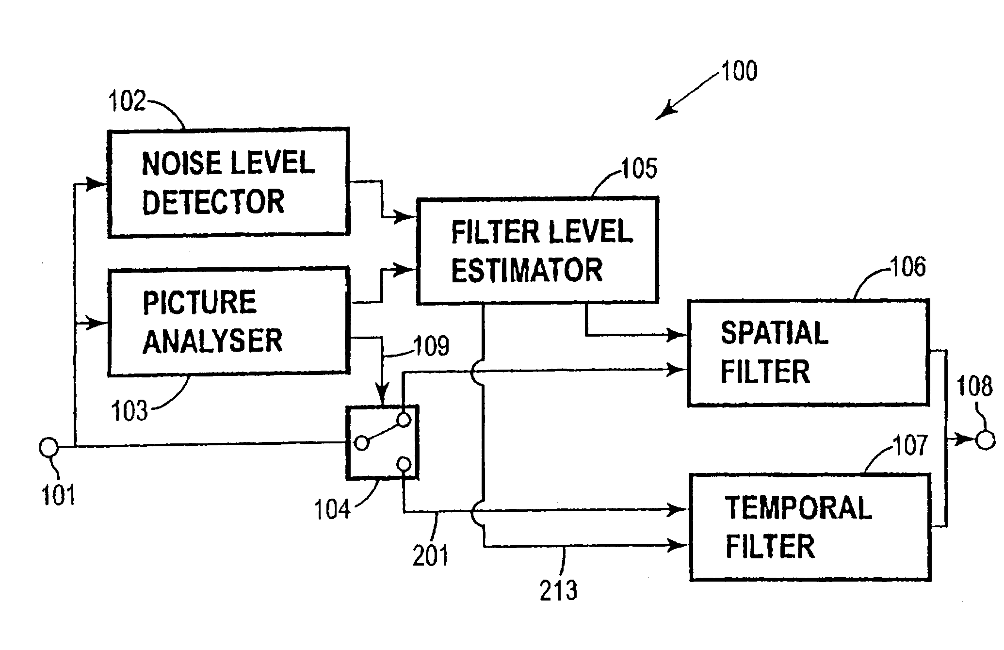
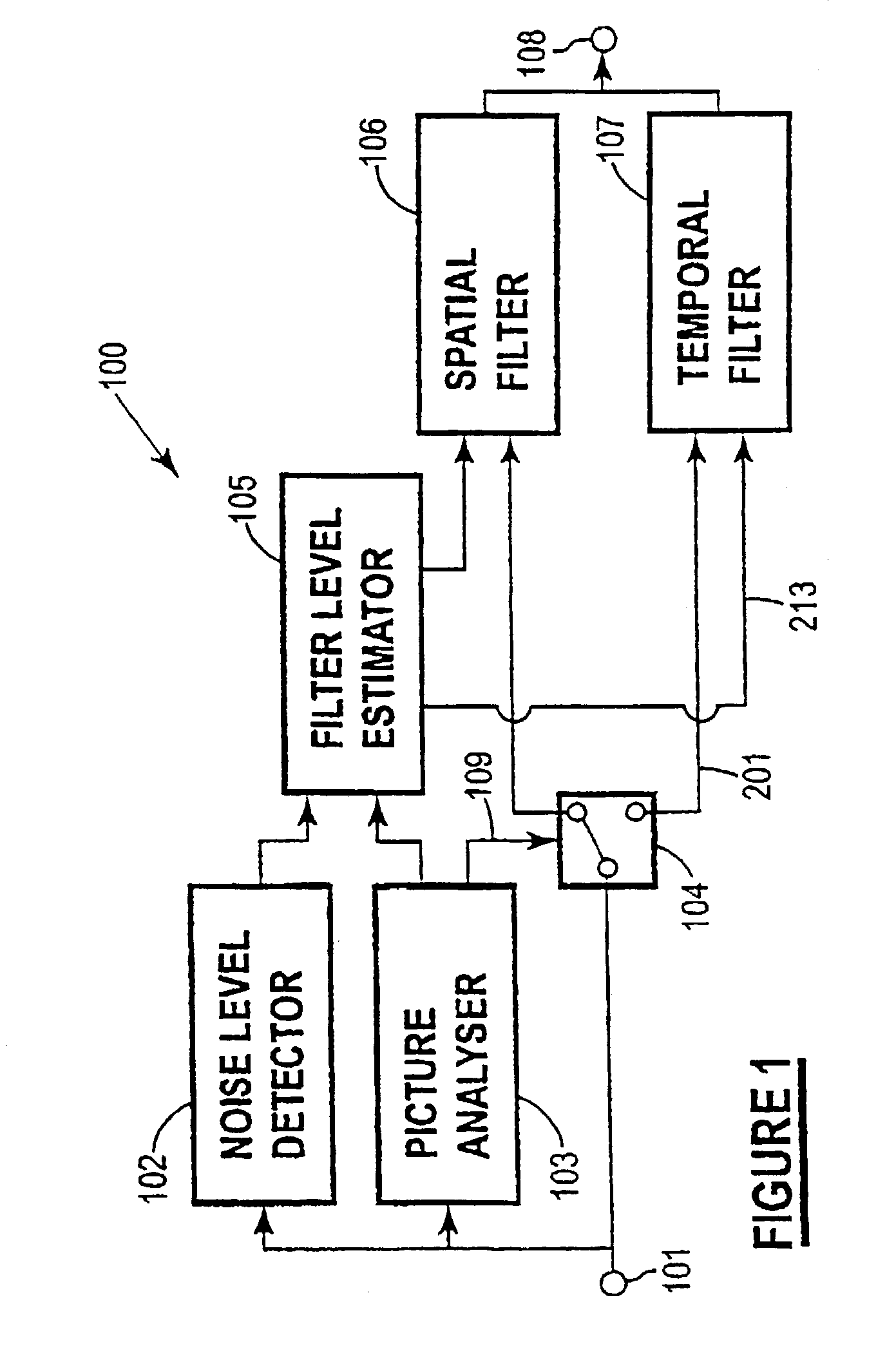
[0021]FIG. 1 is a block diagram of a digital video processing and noise reduction system of the invention;

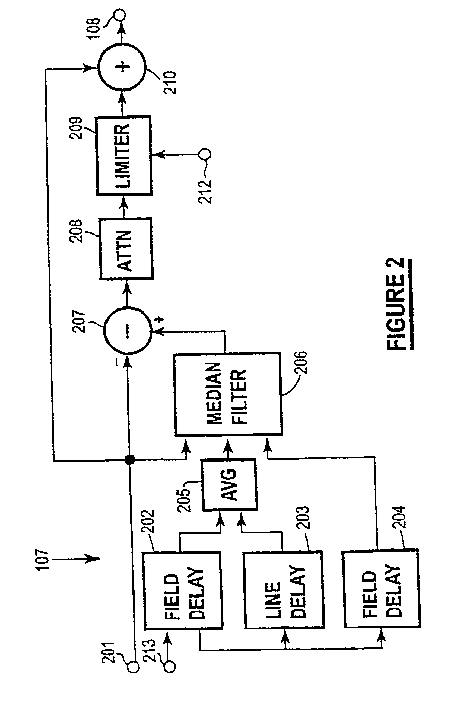
[0022]FIG. 2 is a more detailed block diagram of an embodiment of the temporal filter;

[0023]FIG. 3 is a block diagram of a second embodiment of the digital video processing and noise reduction system;

[0024]FIG. 4 is a block diagram of a filter level estimator circuit;

[0025]FIG. 5 is a more detailed block diagram of part of the circuit shown in FIG. 4;

[0026]FIG. 6 is a histogram of pixel activity; and

[0027]FIG. 7 shows graphically parameters used to estimate contrast activity.

[0028]FIG. 1 shows in block diagram form an embodiment of a digital video processing and noise reduction system 100 of the invention. The major components of the system include a noise level detector 102, picture analyser 103, switch 104, filter level estimator 105, spatial filter 106 and temporal filter 1...


PUM


Abstract

A method and system for digital video noise reduction which includes a picture analyser (103) for analysing pictures in a video sequence to determine the amount of moving regions therein, a noise level detector (102) for estimating the noise level (N) in the video sequence, a filtering level estimator (105, 103) for determining a maximum filtering level (L) for each picture based on the amount of moving regions and the estimated noise level (N) and a spatial filter (106) and a temporal filter (107), the temporal filter being coupled to the filter level estimator for controlling the level of filtering of each picture in the sequence in accordance with the maximum filtering level.

Description

[0001]The present invention relates to digital video processing and noise reduction. It also relates to method and apparatus for improving efficiency in a video encoding system.[0002]Noise reduction techniques have been applied to TV or video signals to improve subjective viewing quality of the signals as well as the compression efficiency in video encoding systems. Such noise reduction techniques include varieties of low-pass filters, median filters, adaptive spatial filters, and temporal recursive filters.[0003]In video sequences with little or no object movement, recursive filters are effective in improving signal-to-noise ratio. One example of temporal recursive noise reduction filter is disclosed in U.S. Pat. No. 5,574,512 and illustrated in FIG. 2. The filter utilises a median filter with input values from current pixel as well as previous field and frame pixels. The median filter allows certain levels of motion adaptive filtering. The amount of filtering is further subjected ...

Claims


Application Information

Patent Timeline
IPC IPC(8): H04N5/21H04N7/26H04N7/36
CPCH04N5/21H04N19/51H04N19/80
Inventor HUI, YAU WAI LUCAS
Owner STMICROELECTRONICS ASIA PACIFIC PTE
Why Eureka
Try Eureka