RF excited gas laser

a laser and excited gas technology, applied in laser cooling arrangements, laser details, active medium materials, etc., can solve the problems of limiting the cooling efficiency of laser tubes, further complicating laser design, and complex flexible tube-to-heat interface assemblies, so as to improve the efficiency of forced air cooling of laser tubes and laser assemblies, and simplify laser tube and laser assembly design , the effect of improving the efficiency of forced air cooling

Inactive Publication Date: 2006-12-05
VITRUK PETER +2
View PDF4 Cites 32 Cited by
  • Summary
  • Abstract
  • Description
  • Claims
  • Application Information

AI Technical Summary

Benefits of technology

[0008]RF excited gas laser according to present invention consists of an elongated electronics compartment having elongated external fins; an RF power supply placed inside electronics compartment; a pair of endplates attached to the opposite ends of the electronics compartment; a sealed laser tube comprising a metal tube having an external surface, a pair of endcaps at the opposite ends of the metal tube forming a vacuum envelope for containing a laser gas, a pair of elongated electrodes inside the metal tube configured for coupling to said RF power supply through RF coupling means; laser resonator mirrors placed on the endcaps at the opposite ends of the tube forming a laser resonator aligned with the RF gas plasma discharge produced between said electrodes; a sheet-metal cover enclosing the laser tube a

Problems solved by technology

At least one side surface of the laser tube faces the heat dissipating power supply electronics compartment, which limits cooling efficiency of the laser tube and is a disadvantage of this design.
In order to prevent laser tube from thermal distortions, it needs to be thermally isolated from electronics compartment, which further complicates laser design.
A disadvantage of all prior art designs is in the complexity of the flexible tube-to-heat interface assemblies.
Another disadvantage of this design is in relative inefficiency of the laser tube cooling because of the close proximity of heat dissipating power supply compart

Method used


Image

  • RF excited gas laser
  • RF excited gas laser
  • RF excited gas laser

Examples


Embodiment Construction

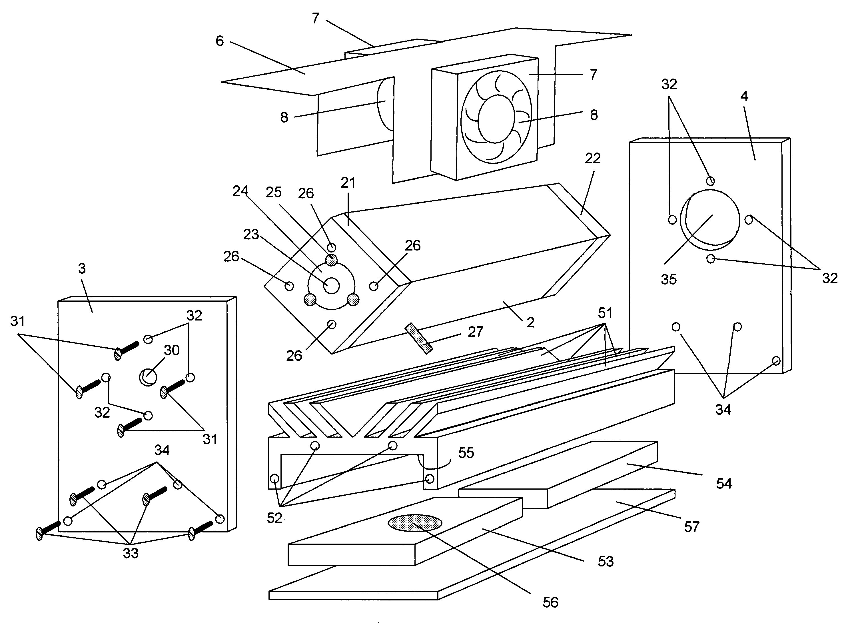
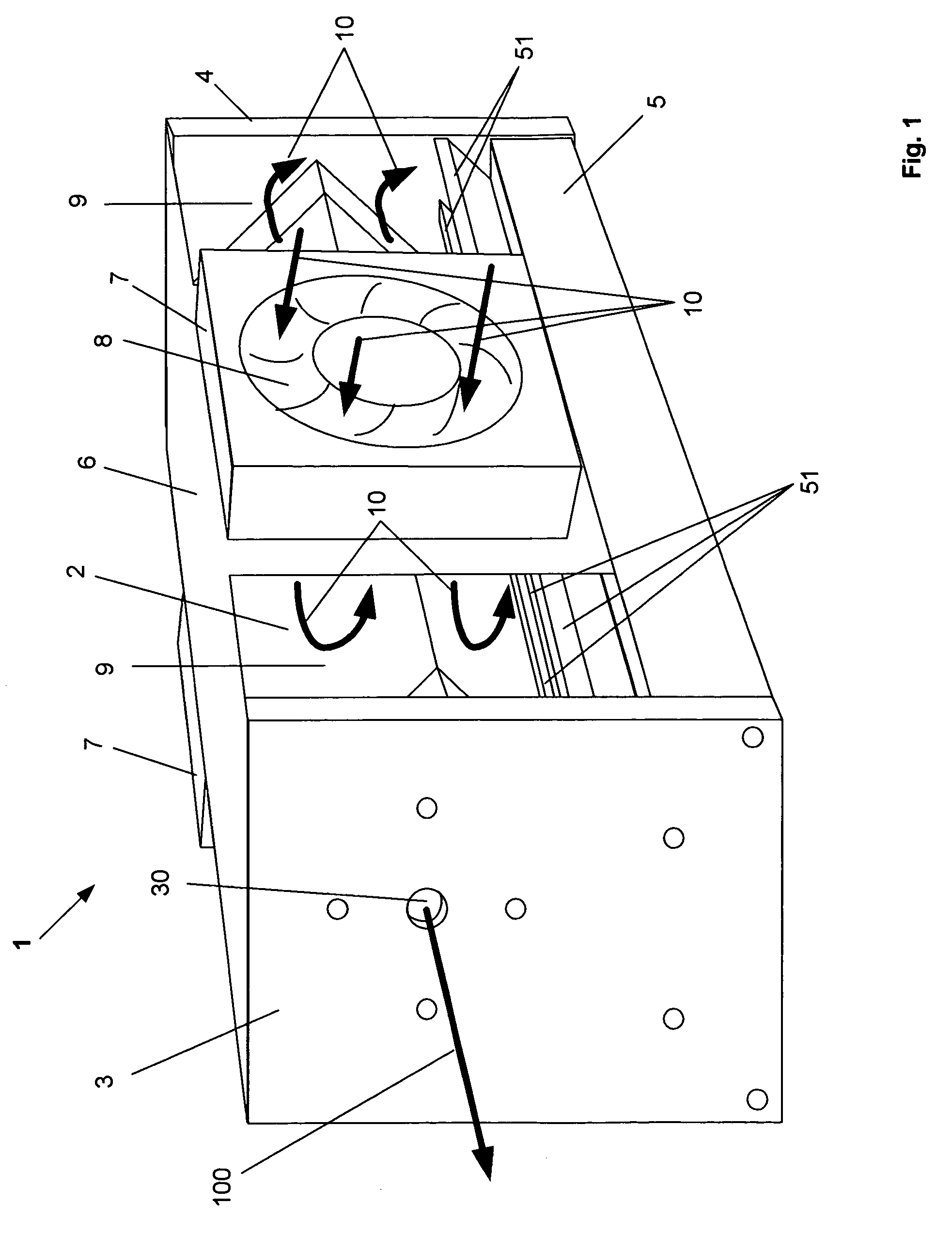
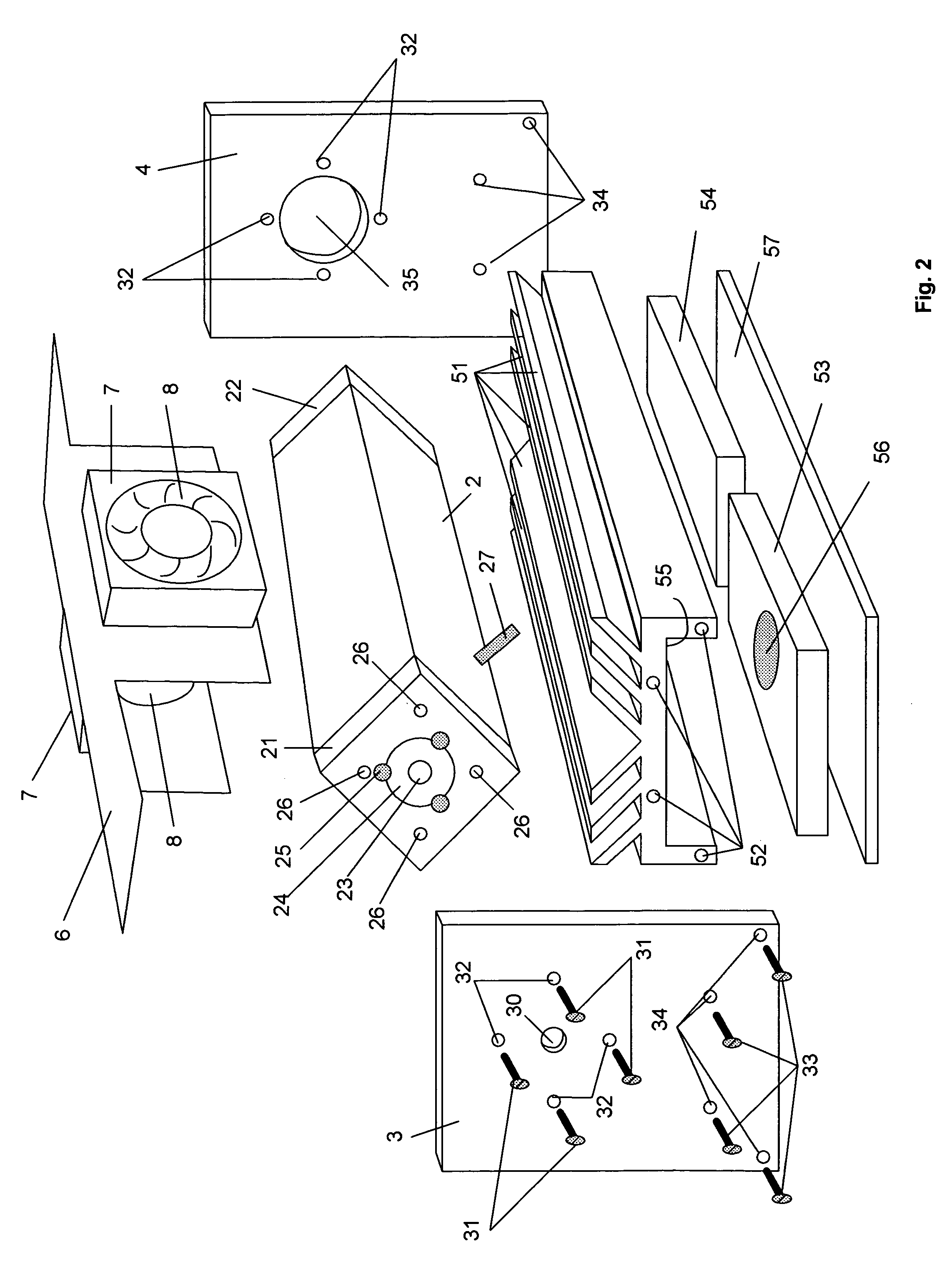
[0015]FIG. 1 is an isometric schematic diagram of RF excited gas laser assembly 1 according to present invention, consisting of laser tube 2 supported by and between front endplate 3 rear endplate 4. Endplates 3 and 4 are mounted on the electronics compartment 5. Sheet metal cover 6 with fans 7 on it is mounted to the endplates 3 and 4 and to the electronics compartment 5 to form air intake openings 8 under the fans 7 and air exhaust openings 9. The cooling air flow 10 enters the laser assembly 1 through the fans 7 and air intakes 8. The cooling air flows over the external surface of the laser tube 2 and over the fins 51 extending off the electronics compartment 5, thus providing an efficient cooling for both the laser tube 2 and electronics compartment 5. The external surface of the laser tube 2 is cooled exclusively by the flow 10 of the cooling air and not by any additional prior-art heat-sinks being in mechanical contact with the external surface of the tube2. Laser beam 100 exi...


PUM


Abstract

RF excited gas laser consists of a laser tube having external surfaces; a power supply compartment having elongated external fins and a pair of endplates on its opposite ends and wherein laser tube is placed between and is flexibly attached to the endplates; a sheet-metal cover mounted to the endplates and to power supply compartment and forming a laser assembly and having at least one pair of intake openings and at least one pair of exhaust openings for the cooling air to flow through the laser assembly by entering the laser assembly through the intake openings and flowing over power supply external fins and over laser tube external surfaces and then exiting through the exhaust openings. Present invention is characterized by lower cost and more efficient forced air cooling laser tube and RF power supply.

Description

REFERENCE TO PROVISIONAL APPLICATION[0001]This application claims the benefit of the U.S. Provisional Application No. 60 / 442,379 filed Jan. 24, 2003.TECHNICAL FIELD[0002]This invention relates to radio-frequency (RF) excited gas lasers, especially to air-cooled low and medium power CO2 lasers.BACKGROUND OF INVENTION[0003]Prior art RF excited gas laser design pioneered by Katherine D. Laakmann (U.S. Pat. No. 4,169,251) defines an elongated laser resonator chamber being excited by transversely applied radio frequency (RF) field.[0004]This basic design of RF excited laser has been further improved by Peter Laakmann (U.S. Pat. No. 4,805,182) through all-metal laser tube arrangement having metal electrodes and metal side-walls forming an elongated laser resonator chamber with electrodes and side-walls being diffusion-cooled by closely spaced walls of the metal tube envelope. Square shaped elongated laser tube is placed inside of the laser housing assembly in such a way that only two (opp...

Claims


Application Information

Patent Timeline
IPC IPC(8): H01S3/04H01S3/03H01S3/041H01S3/0975
CPCH01S3/0315H01S3/03H01S3/0404H01S3/041H01S3/0975
Inventor VITRUK, PETERSCHEMMER, JAMESDIAZ, PAUL
Owner VITRUK PETER
Why Eureka
Try Eureka