Foam forming unit

oam technology, applied in the field of foam forming units, can solve the problems of relatively high cost of manufacturing such a foam forming unit, and achieve the effects of reducing the number of construction components, reducing manufacturing costs, and flexing easily

Inactive Publication Date: 2006-12-12
R D INJECTOR
View PDF13 Cites 40 Cited by
  • Summary
  • Abstract
  • Description
  • Claims
  • Application Information

AI Technical Summary

Benefits of technology

[0008]For this purpose the foam forming unit according to the invention includes a pump for air provided with an inlet having an inlet valve and an outlet having an outlet valve, a pump for liquid provided with an inlet having an inlet valve and an outlet having an outlet valve, a mixing chamber having at least one foam forming element and connected to the outlets of both pumps, and a dispensing part comprising an outflow channel, which is connected between the mixing chamber and a foam opening, wherein at least one of the outlet valves is provided as a thin membrane and integrally formed with a member of said pumps as one piece of the same, preferably plastic, material. By combining interrelated functional elements to a single, integrally formed piece the number of construction components can be reduced, which results in lower manufacturing costs.
[0009]It is specially advantageous to provide the thin membranes of the valves as a cylinder or as a disc, which can be flexed easily by pressure differences.

Problems solved by technology

The cost of manufacturing such a foam forming unit is therefore relatively high.

Method used


Image

  • Foam forming unit
  • Foam forming unit
  • Foam forming unit

Examples


Embodiment Construction

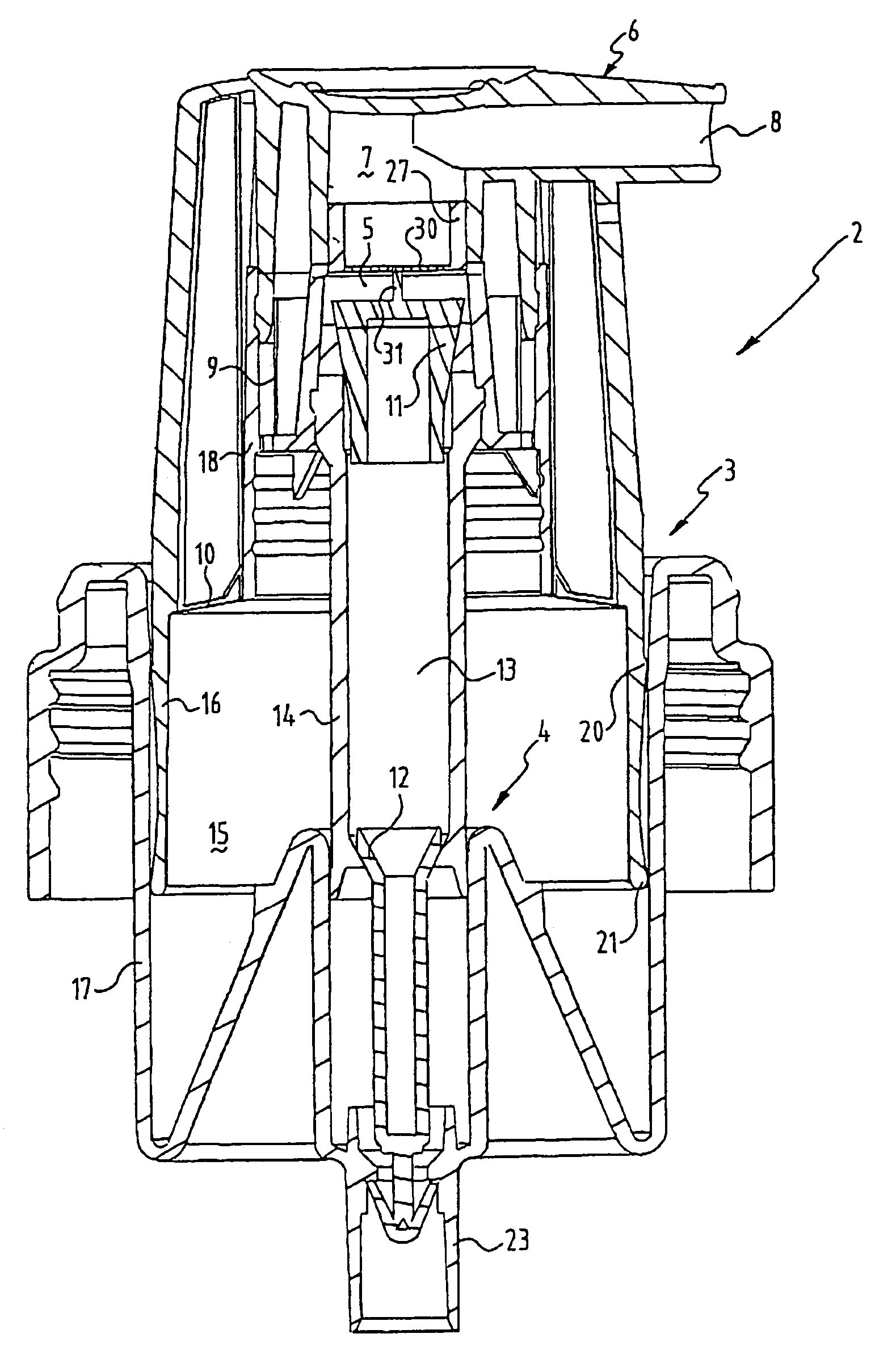
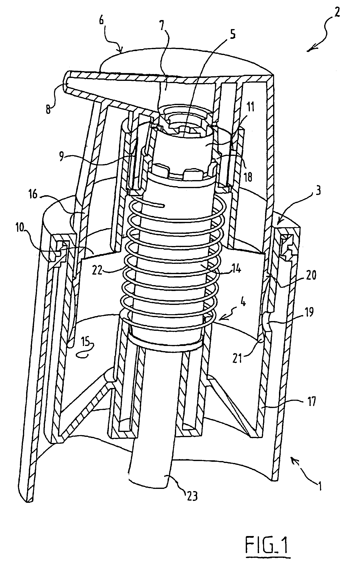
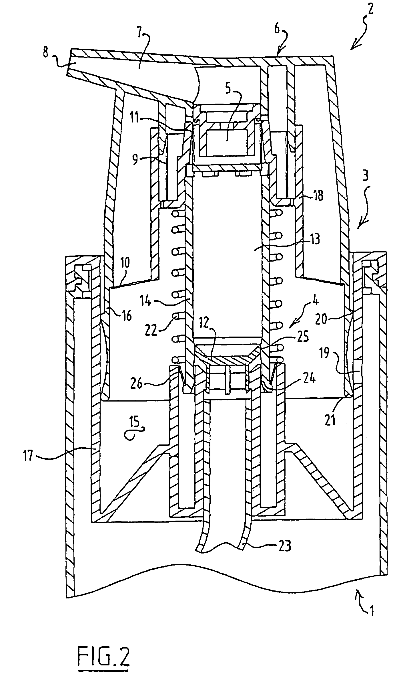
[0016]In the perspective, cross-sectional view of FIG. 1 is shown a foam dispensing assembly consisting of a liquid container 1 and a foam forming unit 2. The foam forming unit 2 comprises a pump 3 for air and a pump 4 for liquid which are each provided with an inlet and an outlet. The inlet of air pump 3 is in communication with the environment, while the inlet of liquid pump 4 is in communication with the content of liquid container 1. Foam forming unit 2 further comprises a mixing chamber 5 which is in communication with the outlet of both air pump 3 and liquid pump 4.

[0017]On the top part of the assembly is situated a dispensing part 6 which is provided with an outflow channel 7 with a foam opening 8. Outflow channel 7 runs from mixing chamber 5 to foam opening 8. One or more foam forming elements are normally located in this channel 7.

[0018]Both the outlet and the inlet of each pump 3,4 are provided with a valve respectively 9,10,11,12 for delivering respectively drawing in air...


PUM


Abstract

A foam forming unit particularly suitable for a liquid container, comprising a pump for liquid and a pump for air, which are each provided with an inlet and an outlet, the foam forming unit further comprising a mixing chamber which is in communication with the outlet of each pump, a dispensing part provided with an outflow channel with a foam opening, the channel being in communication with the mixing chamber, and valves in respectively the inlet and the outlet of each pump for drawing in respectively delivering air and liquid, wherein one or more valves are formed integrally with the air pump or liquid pump into a single construction element.

Description

BACKGROUND OF THE INVENTION[0001]1. Field of the Invention[0002]This invention relates to a foam forming unit for use in combination with a liquid container, including a pump for air and a pump for liquid.[0003]2. Brief Description of the Prior Art[0004]Such a foam forming unit is, for example, known from international patent application WO 99 / 54054, which describes a foam spraying device for a liquid container, having an air suctioning part, a mixture chamber and a spray head with a foam outlet. A first piston-cylinder unit for air and a second piston-cylinder unit for liquid are provided between the spray head and the liquid container. Each unit is fitted with an inlet and an outlet valve. These units are coupled in such a way that they cooperate with each other.[0005]In international patent application WO-A 97 / 13585 a foam dispensing device is described, which comprises a liquid container and operating unit of a concentric air pump and a liquid pump. Each pump has a piston chambe...

Claims


Application Information

Patent Timeline
Patent Type & Authority Patents(United States)
IPC IPC(8): B67D5/58G01F11/00B67D7/76B05B7/00B05B11/00
CPCB05B7/0025B05B11/3074B05B11/3087B05B11/1087B05B11/1074B05B7/00
Inventor BROUWER, MARKUS FRANCISKUSKELDERS, JOHANNES HUBERTUS JOZEF MARIA
Owner R D INJECTOR
Why Eureka
Try Eureka