Liquid accommodation container

a technology of liquid accommodation and container, which is applied in the direction of liquid/fluent solid measurement, instruments, machines/engines, etc., can solve the problems of deviation in amount, inability to accurately determine ink presence and absence, and the arrangement cannot cope with the deviation, etc., to achieve low cost, less expansive, and high reliability

Inactive Publication Date: 2006-12-12
CANON KK
View PDF18 Cites 7 Cited by
  • Summary
  • Abstract
  • Description
  • Claims
  • Application Information

AI Technical Summary

Benefits of technology

[0052]An object of the present invention, which was devised to overcome the conventional cost increasing problem in order to construct the prism remaining amount detection mechanism described above, is to provide a low price ink jet recording apparatus with users as a result that an ink tank (liquid accommodation container), which is less expansive and can detect a remaining amount of ink while operating stably, can be provided. More specifically, an object of the present invention is to provide a highly reliable ink tank at low cost which can detect a remaining amount of ink in an exchangeable ink tank which supplies ink to an ink jet recording head and has an optical reflection mechanism for detecting the remaining amount of ink.
[0061]According to the invention described above, the optical member has such characteristics as to gently changing the intensity of light (FIG. 2) so that the light emitted from a light emitting device of a light sensor is reflected by the optical member while being scattered thereby and incident on a light receiving device of the light sensor. Accordingly, even if a light path (so-called optical axis), which is uniquely determined from the light emitting device to the light receiving device passing through the optical member, is displaced by the influence of a part accuracy and a mounting accuracy, a position alignment accuracy of the light sensor and the liquid accommodation container is eased. With the above arrangement, a remaining amount of a liquid can be more securely detected, and it is not necessary to enhance the position alignment accuracy using a costly means.
[0062]According to the present invention, presence or absence of the liquid remaining in the liquid accommodation container can be sufficiently detected even if the light sensor is not in alignment with the optical axis of the optical member by scattering the light emitted from the light sensor by the optical member. As a result, parts and systems can be simplified, and an ink tank by which the remaining amount can be detected with high reliability can be provided at a low price.

Problems solved by technology

The drawback occurs because the light emitted from a light emitting device is directly reflected on the bottom of the ink tank, on which the prism is disposed, and thus the light receiving device detects the light in an amount larger than an amount which is supposed to be received.
H10-323993, this arrangement cannot cope with the deviation because it is not an arrangement for compensating the deviation.
However, an increase in the amount deviation abruptly decreases an amount of received light, and when the amount of deviation is in the range less than a portion “a” and in the range larger than a point “b” in FIG. 11, the intensity of reflected light has a value less than the threshold value, and thus the ink presence and absence cannot be correctly determined.
To satisfy the above requirements, it is strictly required to assemble the parts and the mechanisms of the prism with a pinpoint accuracy and further it is important to confirm the quality of them, thereby the cost of the prism is inevitably increased.
It is very difficult to accurately mold an optical prism having a complex shape as described above by the injection molding.
Since the surface shape of the prism portion is made uneven by the sink mark, the optical function thereof is deteriorated by it.
Although some plastics are less shrunk in molding and can be selected as materials for overcoming the problem of sink mark described above without the relief, their cost is very expensive.
Further, when a plastic is selected as a material, since the chemical stability of the material to ink must be also taken into consideration, a range of selectable materials is greatly limited.
However, when the amount of emitted light is increased immoderately as shown in FIG. 12, an amount of background reflection 70 is increased by irregular reflection in the ink tank when ink exists therein and background reflected light reaches the light receiving device, from which an error region 71 occurs and an erroneous determination that “ink is absent” is made thereby.
However, it has been difficult to more reduce the cost of the optical remaining amount detection mechanism using the prism because the number of parts is increased to cope with a requirement for a pinpoint accuracy and the quality thereof must be sufficiently managed.

Method used


Image

  • Liquid accommodation container
  • Liquid accommodation container
  • Liquid accommodation container

Examples


first embodiment

(First Embodiment)

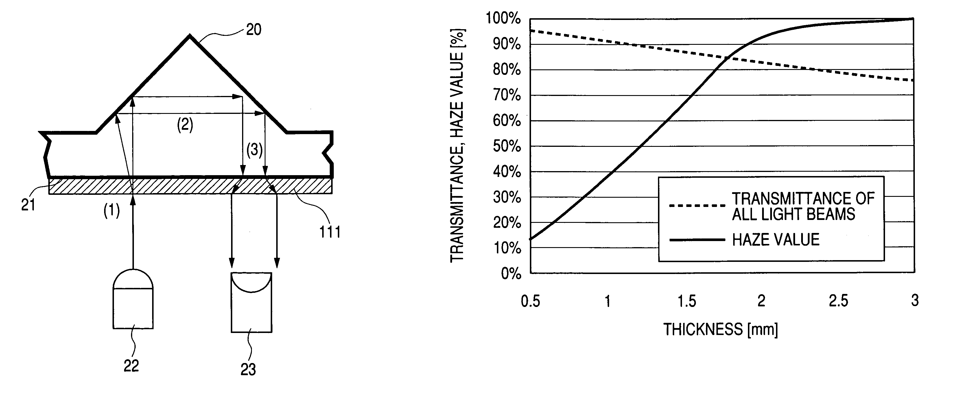
[0076]Table 1 shows the optical characteristics of a material constituting an ink tank and a prism of a first embodiment of the present invention, the optical characteristics of a material constituting a conventional ink tank, and the dimensions of the respective prisms.

[0077]The optical characteristics of the materials constituting the ink tanks were measured according to JIS K7105. Note that since it was difficult to measure the optical characteristics of the material of a prism portion of the ink tank due to its shape, they were measured as to the wall portion constituting the ink tank other than the prism portion. The wall of the ink tank measured in the embodiment had a thickness “t” of 1.7 mm.

[0078]

TABLE 1TransmittancePrismof all lightDiffusionHazeheightbeamsratiovalueConventional3.2 mm81%22%27%containermaterialVessel3.2 mm88%70%80%material ofEmbodiments

[0079]It can be found that the material used in the embodiments is a resin having a feature that it has a h...

second embodiment

(Second Embodiment)

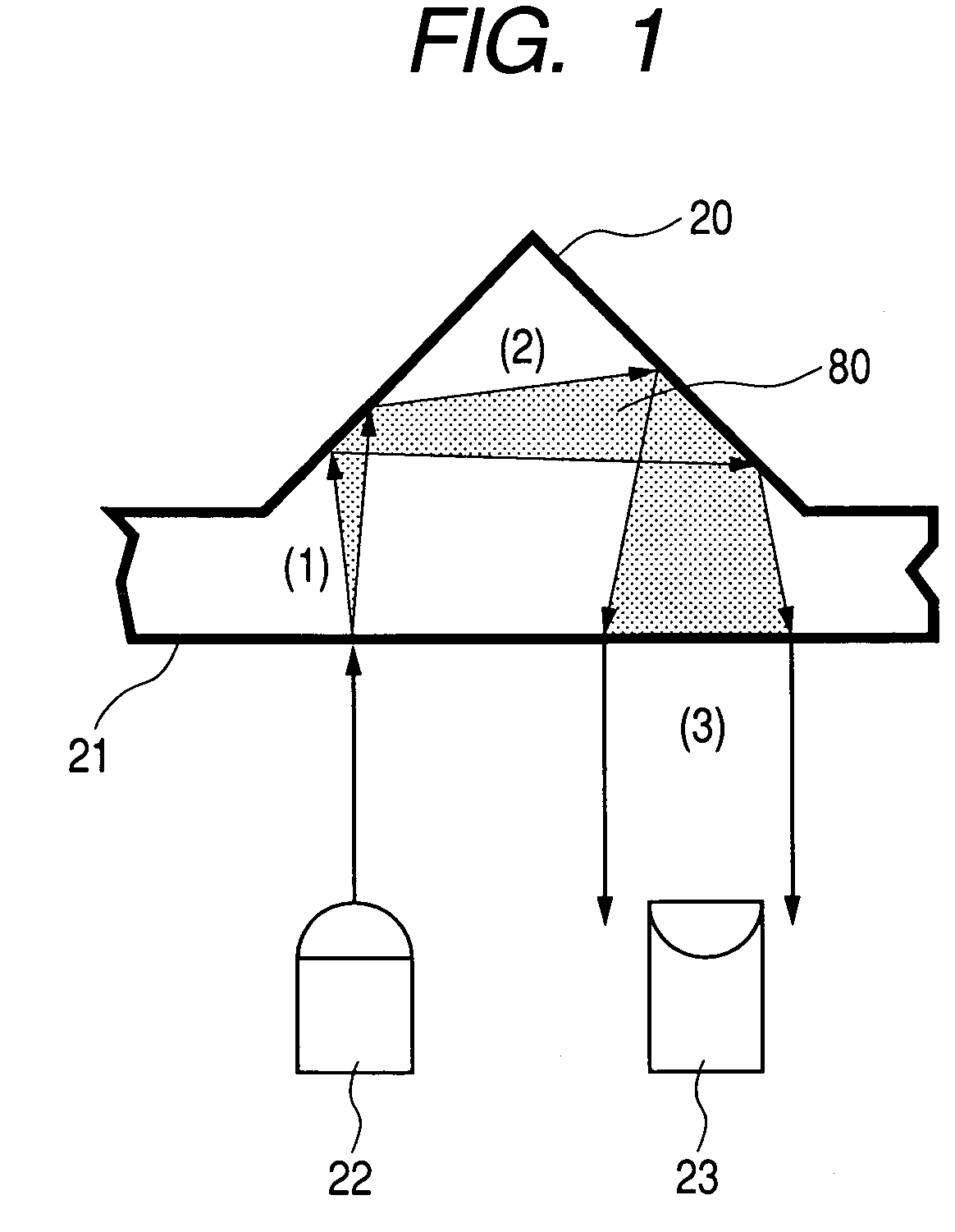
[0089]FIG. 3 shows a behavior of light traveling in a prism 20 of an ink tank according to a second embodiment of the present invention.

[0090]The second embodiment shows an example that light is scattered while maintaining the degree of transparence of a material itself constituting the prism 20 to a conventional value (for example, a Haze value of 27%).

[0091]The second embodiment intends to disperse light by intentionally reducing the degree of flatness of the surfaces 100, 101, and 102 of the prism 20. When the prism 20 is formed of plastic by injection molding, the prism 20 can be formed in a shape, which can disperse light on the surfaces thereof, by a design of a metal mold. The portions of the prism 20, which are subjected to a non-mirror-finished surface treatment and formed to rough surfaces, are the surfaces 100 and 101 that are two slanting surfaces thereof and at least the surface 102 of the wall of the ink tank which corresponds to the portion of the i...

third embodiment

(Third Embodiment)

[0093]FIG. 4 shows a behavior of light traveling in a prism 20 of an ink tank according to a third embodiment of the present invention.

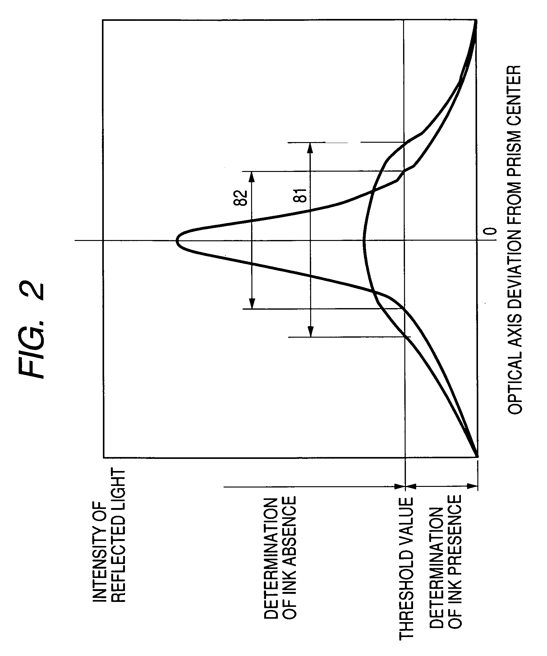
[0094]In the third embodiment, a light dispersing sheet 111 for dispersing light is disposed on the portion of the bottom 21 of the ink tank which corresponds to at least the prism 20. The basic structure of the ink tank is the same as that of the conventional ink tank (refer to FIGS. 7A and 7B), and the dispersion of light can be finely adjusted by selecting the light dispersing sheet 111 bonded to the prism 20 depending on a type and sensitivity of the sensors of a light emitting device 22 and a light receiving device 23 and on a threshold value for determining ink presence and absence.

[0095]It is supposed that a test piece, which has a square cross section with each side of 40 mm and a thickness of 1.7 mm and to which the above sheet is bonded, has a transmittance of all light beams of 80% or more and a Haze value equal to or mor...


PUM


Abstract

A prism of an ink tank has a function for reflecting light, which is incident from the outside, to the outside when no liquid is present in a liquid chamber and not reflecting the light, which is incident from the outside, to the outside when a liquid is present in the liquid chamber, and when the optical characteristics of a material constituting the liquid accommodation container are measured based on a standard according to JIS K7105, the material has optical characteristics equivalent to such optical characteristics that a transmittance of all light beams is 80% or more and a Haze value is equal to or more than 75% and equal to or less than 85%. With the above arrangement, there can be provided an ink tank, which can be operated stably and detect a remaining amount of ink, at a low price.

Description

[0001]This application claims priority from Japanese Patent Application No. 2003-280025 filed on Jul. 25, 2003, which is hereby incorporated by reference.BACKGROUND OF THE INVENTION[0002]1. Field of the Invention[0003]The present invention relates to a structure of a liquid accommodation container for accommodating ink and the like, and more particularly, to an ink tank of a recording apparatus on which a cartridge, which includes a recording head for executing recording according to an ink jet system and the ink tank for supplying ink to the recording head, is mounted.[0004]2. Description of the Related Art[0005]There has been known an arrangement disclosed in, for example, Japanese Patent Application Laid-Open No. H8-112907 as a method of detecting a remaining amount of ink or the presence or absence of ink in an ink tank (liquid accommodation container) for accommodating a liquid such as ink and the like, that is, as a method of optically detecting the presence of ink. Japanese P...

Claims


Application Information

Patent Timeline
Patent Type & Authority Patents(United States)
IPC IPC(8): B41J2/175
CPCB41J2/17566B41J2002/17573B41J2/17503
Inventor UJITA, TOSHIHIKO
Owner CANON KK
Why Eureka
Try Eureka