Connecting structure of flexible printed circuit board to printed circuit board

a flexible printed circuit board and connecting structure technology, applied in the direction of fixed connections, printed circuit aspects, coupling device connections, etc., can solve the problems of connection between patterns and complicating the shape of flexible circuit boards

Inactive Publication Date: 2006-12-12
FUNAI ELECTRIC CO LTD
View PDF6 Cites 13 Cited by
  • Summary
  • Abstract
  • Description
  • Claims
  • Application Information

AI Technical Summary

Benefits of technology

[0012]The present invention has been made in consideration of the above-described problems, and an object thereof is to provide a simple connecting structure for connecting a flexible printed circuit board to another printed circuit board, which structure provides ease in positioning so that the connection therebetween can be made smoothly and rigidly, and further the assembling time can be reduced.
[0017]In the first embodiment, the leading edge portion of the flexible printed circuit board, which is left between the cut portions, is bent downward to be inserted into the elongate hole and the rectangular holes of the printed circuit board, which allows the flexible printed circuit board to be easily positioned against the other printed circuit board. It is also possible to connect the boards smoothly and rigidly with such a simple structure, and further to reduce the assembling time. In particular, the leading edge portion of the flexible printed circuit board, which is left between the cut portions and inserted into the elongate hole and the rectangular holes of the printed circuit board, is curved, which allows the leading edge portion to be held and connected rigidly.
[0018]Preferably, the leading edge portion of the flexible printed circuit board, which is left between the cut portions, is bent downward to be inserted into the elongate hole of the printed circuit board, which allows the flexible printed circuit board to be easily positioned against the printed circuit board easily. It is also possible to connect the boards smoothly and rigidly with such a simple structure, and further to reduce the assembling time.
[0019]In another preferred embodiment, the leading edge portion of the flexible printed circuit board, which is left between the cut portions, is inserted into the elongate hole and the rectangular holes of the printed circuit board in a curved manner, which allows the leading edge portion to be held and connected rigidly.
[0020]In yet another preferred embodiment, the tapered cut portions are provided in the leading edge portion of the flexible printed circuit board, which is left between the cut portions, which allows the leading edge portion left between the cut portions to be inserted into the elongate hole or the elongate hole as well as the rectangular holes of the printed circuit board smoothly.

Problems solved by technology

However, the patterns 104 on the flexible printed circuit board 103 are manually aligned with the patterns 102 on the printed circuit board 101, resulting in a problem in that hand movement, etc. can make the positioning and therefore the connection between the patterns 102 and 104 by the soldering 105 difficult.
However, the above connecting structure suffers from a problem in that when the flexible circuit board 210 is lifted upward, the bent portions 213 can easily be removed from the engaging holes 211d.
However, the arrangement described above suffers from a problem in that part of the electrode patterns 304 must be formed on the underside surface of the circuit board 301, that is, the circuit board 301 must be double-sided.
However, the arrangement above suffers from a problem in that the engaging portion 405 should be formed projecting downward from the flexible circuit board 402, which complicates the shape of the flexible circuit board 402.

Method used


Image

  • Connecting structure of flexible printed circuit board to printed circuit board
  • Connecting structure of flexible printed circuit board to printed circuit board
  • Connecting structure of flexible printed circuit board to printed circuit board

Examples


first embodiment

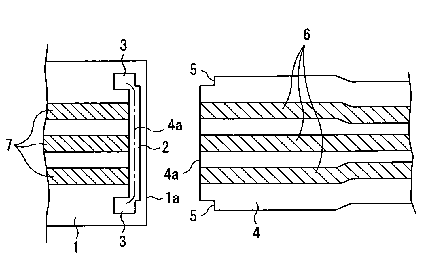
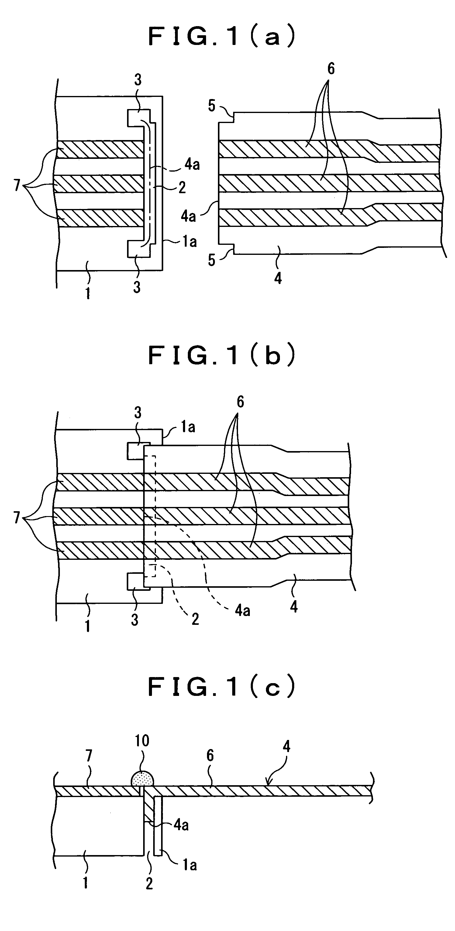
[0028]In the connecting structure for connecting a flexible printed circuit board to another printed circuit board as shown in FIG. 1 (a), an elongate hole 2 is formed in the vicinity of and along an edge portion 1a in a connecting part of a printed circuit board 1, and two rectangular holes 3 communicating with the elongate hole 2 are formed at both longitudinal ends of the elongate hole 2, while two cut-outs (notches) 5 for controlling insertion depth are provided at both corners of the connecting edge of the flexible printed circuit board 4.

[0029]As shown in FIGS. 1 (b) and 1 (c), the leading edge portion 4a of the flexible printed circuit board 4, which is left between the notches 5, is bent downward, and the bent portion is inserted into the elongate hole 2 and the rectangular holes 3 of the printed circuit board 1 to position the flexible printed circuit board 4, and then patterns 6 on the flexible printed circuit board 4 and patterns 7 on the printed circuit board 1, which f...

second embodiment

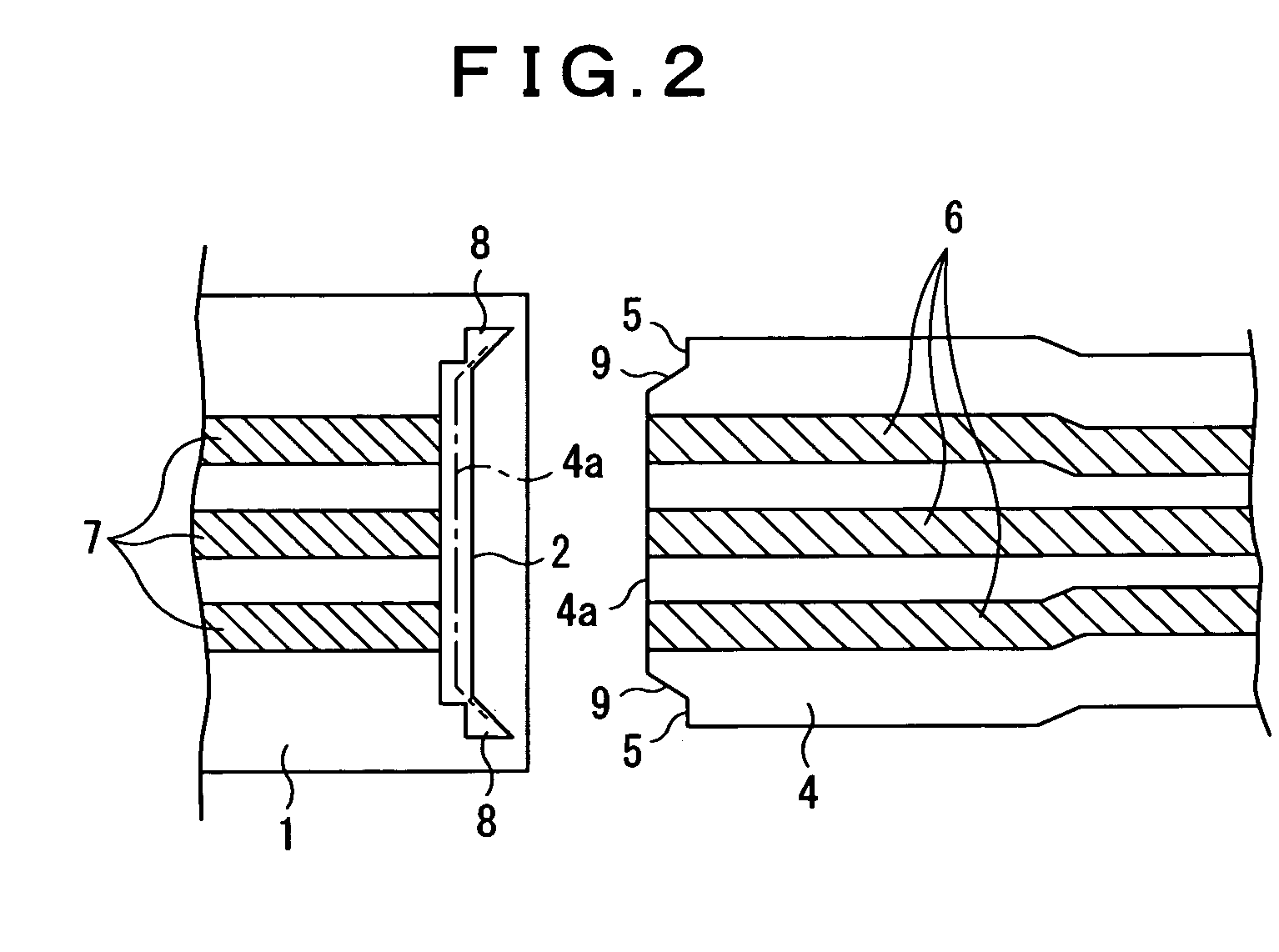
[0032]In the connecting structure of the flexible printed circuit board to the printed circuit board as shown in FIG. 2, two rectangular holes 8 communicating with the elongate hole 2 are formed toward the edge portion 1a in both longitudinal end portions of the elongate hole 2 of the printed circuit board 1. Further, two tapered cut portions 9 which narrow toward the connecting edge are provided on both ends of the leading edge portion 4a of the flexible printed circuit board 4, which is left between the cut portions 5.

[0033]The leading edge portion 4a of the flexible printed circuit board 4, which is left between the cut portions 5, is bent downward, and the bent edge portion 4a is inserted into the elongate hole 2 and the rectangular holes 8 of the printed circuit board 1 to connect the patterns 6 on the flexible printed circuit board 4 and the patterns 7 on the printed circuit board 1 by soldering.

[0034]Therefore, in accordance with the second embodiment, the leading edge porti...


PUM


Abstract

The present invention provides a simple structure for connecting a flexible printed circuit board to a printed circuit board in which when connecting a flexible printed circuit board to a printed circuit board, the positioning thereof can be made easily, the connection therebetween can be made smoothly and rigidly, and further the assembling time can be reduced. Patterns, on a flexible printed circuit board and a printed circuit board are aligned and connected with each other by soldering. An elongate hole is formed in the vicinity of and along the edge portion in a connecting part of the printed circuit board, and two rectangular holes communicating with the elongate hole are formed at both longitudinal ends of the elongate hole, while two notches for controlling insertion depth are provided at opposing ends of the connecting edge of the flexible printed circuit board. The leading edge portion of the flexible printed circuit board, which is left between the cut portions, is bent downward, and the bent portion is inserted into the elongate hole and the rectangular holes of the printed circuit board to position the flexible printed circuit board, and then the patterns, respectively located on the flexible printed circuit board and the printed circuit board, are connected by soldering.

Description

CROSS-REFERENCE TO RELATED APPLICATIONS[0001]This application claims priority, under 35 USC 119, of Japanese Application No. 2004-132,701, filed Apr. 28, 2005, the teachings of which are incorporated herein in their entirety.BACKGROUND OF THE INVENTION[0002]1. Field of the Invention[0003]The present invention relates to a connecting structure for connecting a flexible printed circuit board to another printed circuit board, in which patterns are aligned to allow the printed circuit boards to be connected by soldering.[0004]2. Description of the Prior Art[0005]In one conventional connecting structure patterns 104 on a flexible printed circuit board 103 are aligned with patterns 102 on a printed circuit board 101 and the patterns 102 and 104 are connected by soldering 105, as shown in FIG. 3. However, the patterns 104 on the flexible printed circuit board 103 are manually aligned with the patterns 102 on the printed circuit board 101, resulting in a problem in that hand movement, etc. ...

Claims


Application Information

Patent Timeline
Patent Type & Authority Patents(United States)
IPC IPC(8): H01R12/00H01R13/631H05K1/11H05K1/14H05K3/36
CPCH01R12/61H01R23/661H05K3/363H01R13/631H05K2201/048H05K2201/09063H05K2201/091H01R12/772H01R12/62
Inventor IKEDA, AIICHIRO
Owner FUNAI ELECTRIC CO LTD
Why Eureka
Try Eureka