Method and apparatus for friction stir welding

a technology of friction stir welding and friction stir, which is applied in the direction of soldering apparatus, manufacturing tools,auxillary welding devices, etc., can solve the problems of short but deep cracks in the surface of the backing means, inability to meet the joint, and the welding probe to break, so as to prolong the service life of the welding probe and increase the quality of the formed joint. , the effect of increasing productivity

Inactive Publication Date: 2006-12-19
ESAB AB
View PDF10 Cites 20 Cited by
  • Summary
  • Abstract
  • Description
  • Claims
  • Application Information

AI Technical Summary

Benefits of technology

[0011]One object of the present invention therefore is to provide a method and an apparatus for friction stir welding by means of which it becomes possible to substantially prolong the serviceable life of said welding probe. It is likewise desirable to simultaneously increase the quality of the formed joint, primarily by securing safe weld penetration and complete fusion via the base material, and in addition thereto increase productivity.
[0014]Due to the supply of additional heat to the joint between the workpieces in excess of the frictional heat generated through the rotation of the welding means and any other heat that may be supplied to the joint by the welding means in any other manner, the serviceable life of the welding probe is prolonged considerably. In cases when the joint is backed up by means of a subjacent backing means, cracking of the latter is also prevented, if heat is supplied to the joint by way of the backing means. The difference is pronounced and is a prerequisite for the welding of for instance several aluminum alloys with acceptable economy. In addition, higher welding quality is obtained because of improved penetration and safer bonding against the base material, and it also becomes possible to increase the welding speed with consequential higher productivity.

Problems solved by technology

One of the problems encountered in friction stir welding of hard-to-weld materials, such as aluminum alloyed with magnesium, with lithium or with copper, is that the forces deployed during the welding operation are of such a magnitude as to cause the welding probe to break after a comparatively short period of welding, as a result of fatigue.
Another problem is the generation of short but deep cracks in the surface of the backing means, particularly in the transverse direction of the latter, due to thermal fatigue.
Because the joint, owing to the plasticisation thereof during the welding operation, will adopt the appearance of the backing means surface, these cracks will manifest themselves as protrusions on the lower face of the joint, and as a result the joint will be unacceptable.
A further problem is that the frictional heat generated in hard-to-weld materials may be insufficient, and that consequently complete weld penetration is not achieved, or that lack of fusion will occur.

Method used


Image

  • Method and apparatus for friction stir welding
  • Method and apparatus for friction stir welding

Examples


Embodiment Construction

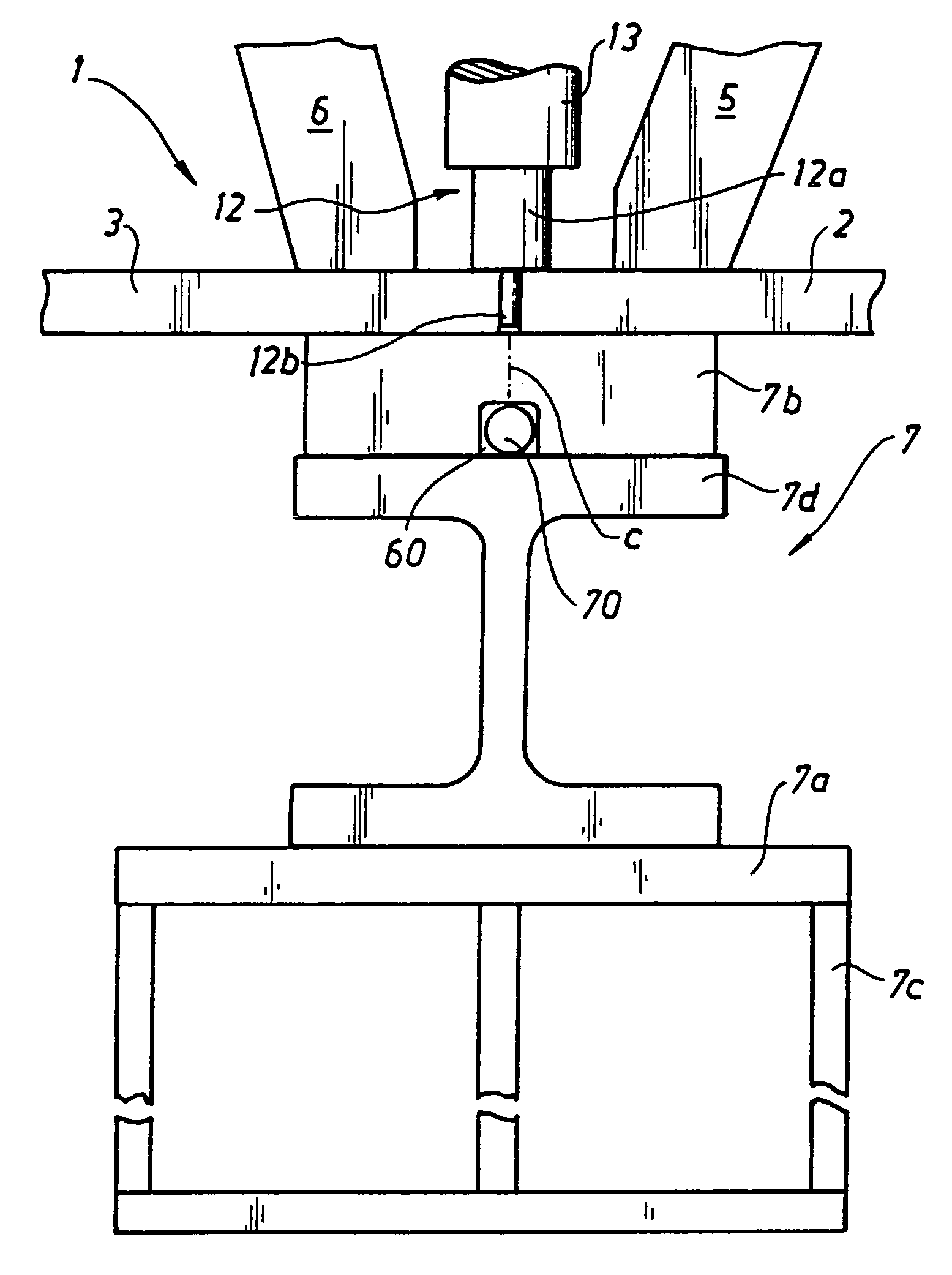
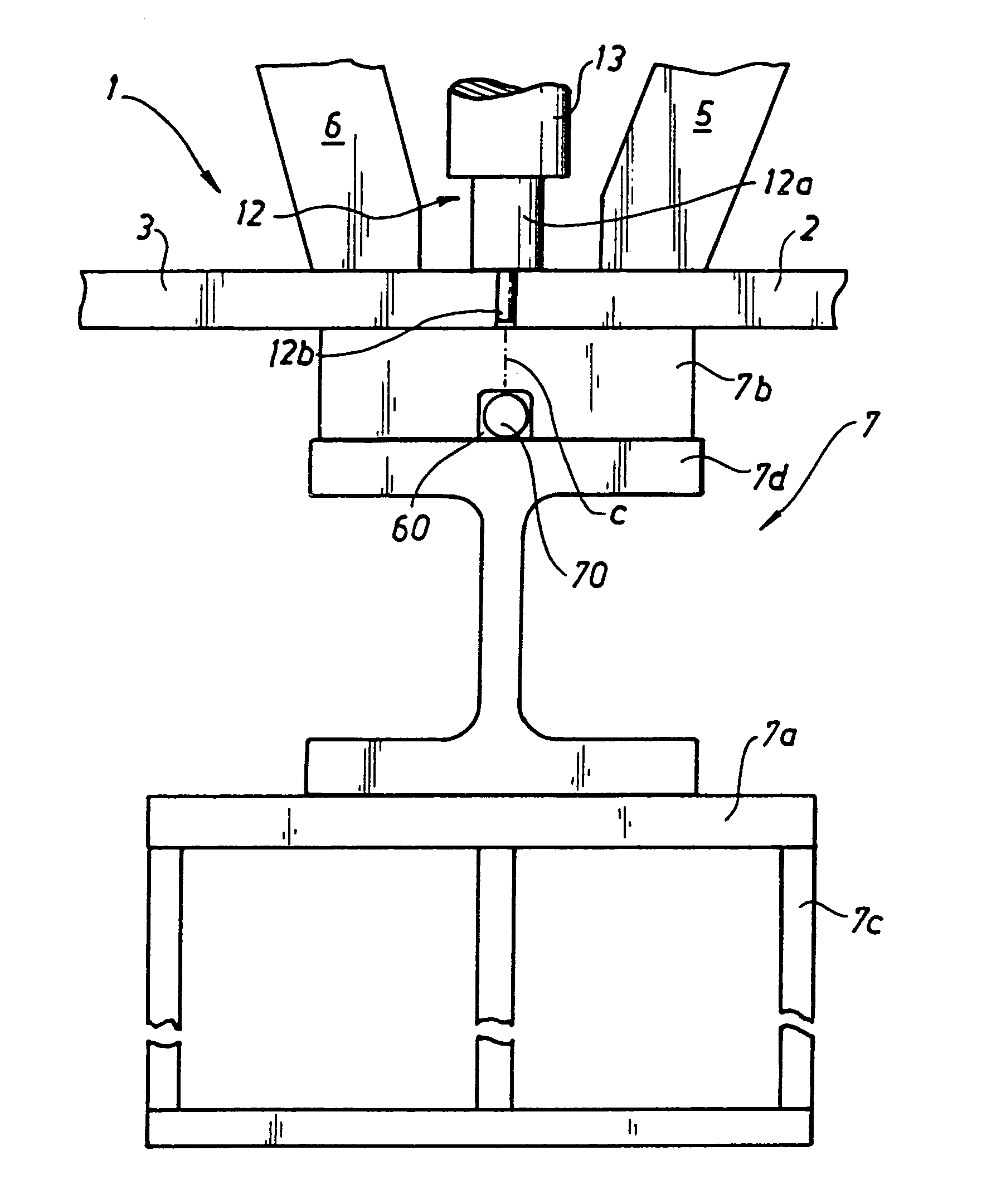
[0017]The apparatus 1 shown in the drawing figure is intended for welding together two workpieces 2, 3, the latter being e.g. extruded aluminum profile sections.

[0018]During the welding operation, the workpieces 2, 3 are secured to the work-table 7 by clamping means 5 and 6, respectively. The clamping means 5 and 6, respectively, may consist of a compression cylinder. The present work-table is a horizontal machine table 7a to which a backing means 7b is stationarily secured by means of a backing bar 7d in the shape of an I-beam and which is supported by a stationary, rigid frame 7c. The backing means 7b is formed with a groove 60 extending in the longitudinal direction of the support, laid groove having received therein a heating coil in the form of a heating cable 70.

[0019]The joint between the workpieces 2, 3 is placed in alignment with the centre line of the backing means. The backing means backs up also the edges of the joint and prevents the plasticized material from flowing aw...


PUM

PropertyMeasurementUnit
Temperatureaaaaaaaaaa

Abstract

The invention concerns a friction stir welding method according to which the workpieces (2, 3) to be welded are positioned on a worktable (7) and by means of clamping means (5, 6) clamped to one another and / or to the work-table during the welding. A rotating welding means (12, 13) is arranged to move along a joint between the work pieces while being pressed against said workpieces during the welding. Additional heat is supplied to the joint prior to and / or during the welding operation, in excess of the frictional heat generated in the joint from the rotation of the welding means and of any other heat hat may be supplied to the joint in any other manner by the welding means. The invention likewise concerns an apparatus for friction stir welding, comprising a heat element (70) for supply of additional heat to the joint prior to and / or during the welding operation, in excess of the frictional heat generated in the joint from the rotation of the welding means and of any other heat that may be supplied to the joint in any other manner by the welding means.

Description

BACKGROUND OF THE INVENTION[0001]1. Field of the Invention[0002]The present invention relates to a friction stir welding method according to which the workpieces to be welded are positioned on a work-table and by means of clamping means clamped to one another and / or to the worktable and according to which a rotating welding means is arranged to move along a joint between the workpieces while being pressed against said workpieces during the welding.[0003]The present invention likewise relates to an apparatus for friction stir welding, comprising a worktable supporting the workpieces to be welded, at least one clamping means for clamping the workpieces to one another and / or to the work-table, and a welding means adapted to be advanced along a joint between the workpieces while being pressed against said workpieces during the welding.[0004]2. Description of Related Art[0005]The definition friction stir welding designates a welding method according to which the workpieces to be joined t...

Claims


Application Information

Patent Timeline
IPC IPC(8): B23K31/02B23K20/12B23K20/26
CPCB23K20/126B23K20/12
Inventor KNIPSTROM, KARL-ERIKMALM, ANDERS
Owner ESAB AB
Why Eureka
Try Eureka