Sleep state estimation device and program product for providing a computer with a sleep state estimation function

a technology of sleep state estimation and program product, which is applied in the field of sleep state estimation device and program product for providing a computer with a sleep state estimation function, can solve the problems of ecg measurement, complicated measurement process, and plural electrodes, and achieve the effect of relative simplicity

Inactive Publication Date: 2006-12-19
SANYO ELECTRIC CO LTD
View PDF13 Cites 60 Cited by
  • Summary
  • Abstract
  • Description
  • Claims
  • Application Information

AI Technical Summary

Benefits of technology

[0007]The present invention has been made in view of the above, and an object of the present invention is therefore to provide a sleep state estimation device capable of estimating a sleep state in real time with relative simplicity. To attain this object, the present invention focuses on the relation between respiratory movement and sleep state, and estimates the sleep state (deep sleep, light sleep) based on regular or irregular variations of respiratory movement.

Problems solved by technology

Measurement by ECG, however, has a drawback in that plural electrodes have to be attached directly to the skin of a subject, restraining the subject with their codes which are connected to ECG equipment.
Non-restrictive measurement therefore needs FFT and filter computation processing for frequency analysis as well as signal amplification processing, which complicate the measurement process.

Method used


Image

  • Sleep state estimation device and program product for providing a computer with a sleep state estimation function
  • Sleep state estimation device and program product for providing a computer with a sleep state estimation function
  • Sleep state estimation device and program product for providing a computer with a sleep state estimation function

Examples


Embodiment Construction

[0028]An embodiment of the present invention is described below with reference to the drawings. The following embodiment is merely an example of the present invention, and is not to limit the scope of the invention.

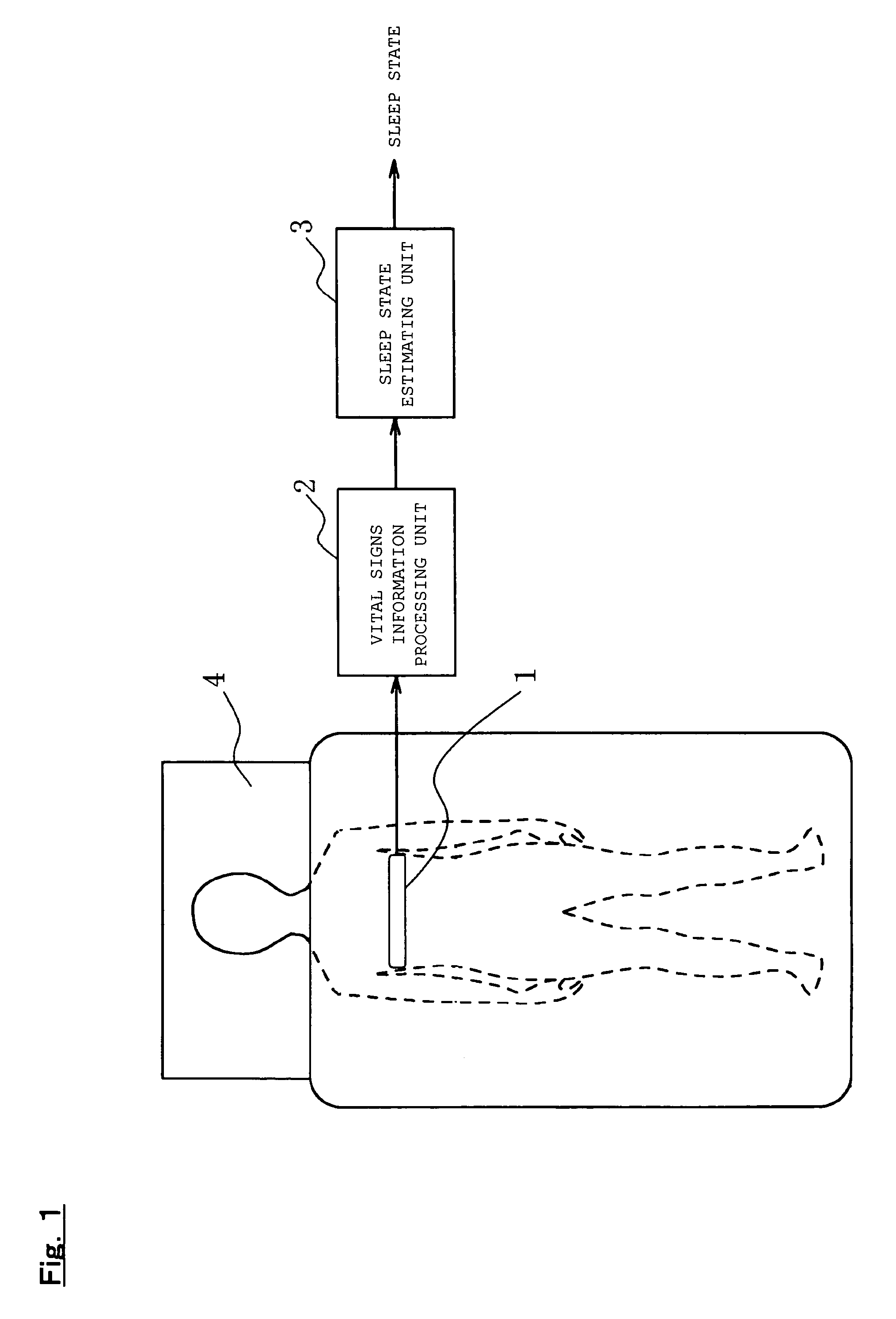
[0029]Referring to FIG. 1, a sleep state estimation device according to the present embodiment is composed of a respiratory band 1, which is one of vital signs information sensors, a vital signs information processing unit 2, and a sleep state estimating unit 3. In FIG. 1, a person is lying on a mattress 4 with the respiratory band 1 attached to his / her upper body.

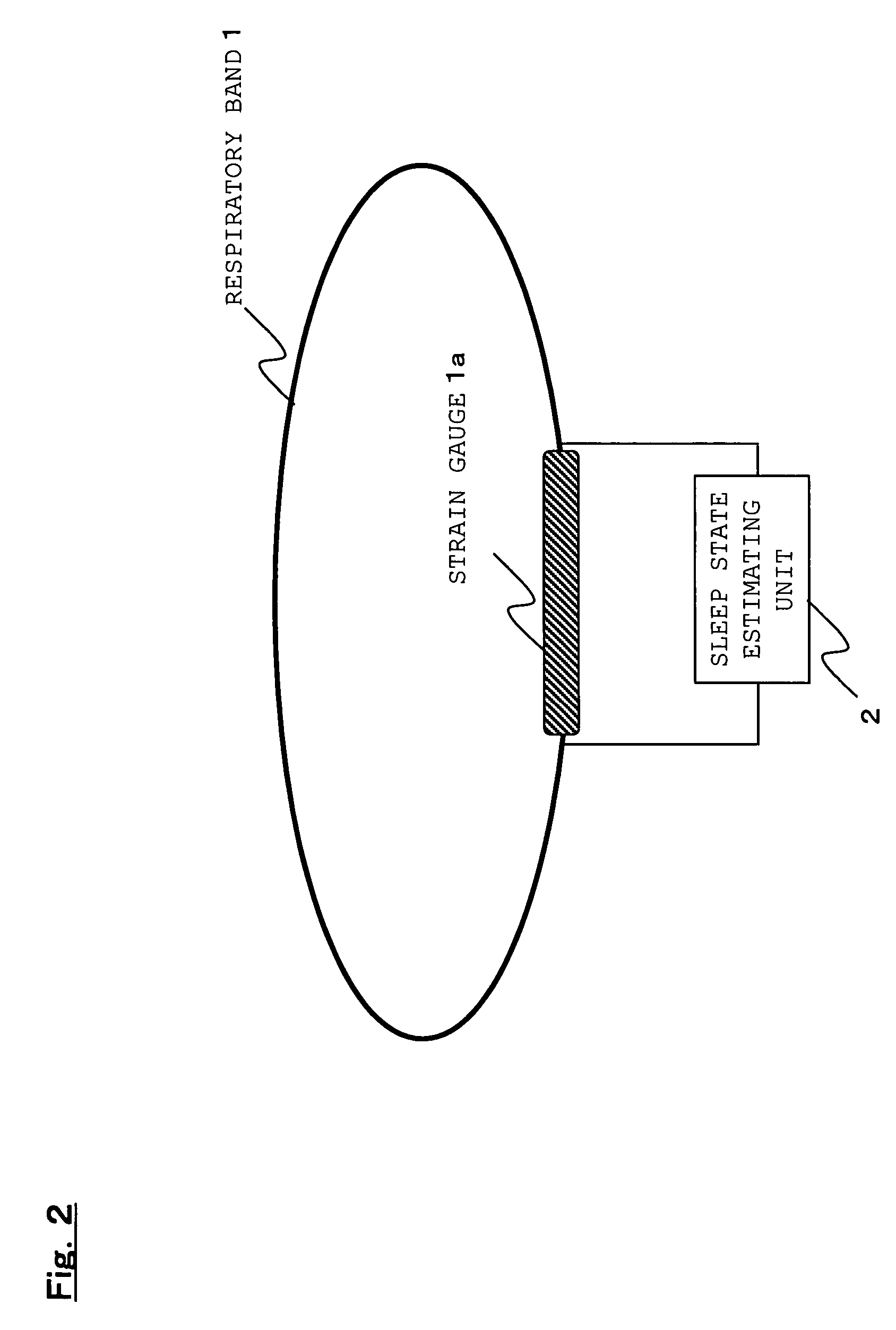
[0030]The respiratory band 1 is, as shown in FIG. 2, an elastic band having a strain gauge 1a. The strain gauge 1a is made from, for example, a carbon tube or a zinc sulfate solution tube. The respiratory band 1 is wound around the chest or abdominal area of the subject, and respiratory movement of the subject expands and contracts the strain gauge 1a, thereby changing the electric resistance of the gauge.

[0031]...


PUM


Abstract

An object of the present invention is to provide a sleep state estimation device capable of estimating a sleep state (deep sleep, light sleep) in real time with relative simplicity. Voltage variations resulting from human respiratory movement are measured for each given period to calculate from the measurement results positive voltage peak values and time intervals between adjacent peaks. The obtained peak values and peak intervals are used to calculate a mean peak interval value A, a coefficient of variation B based on dispersion of the peak intervals, and a coefficient of variation C based on the peak values. The sleep state in this period is estimated from the calculation results. More specifically, referring to FIG. 5, the sleep state is estimated as a “wakeful state” or a “hypnagogic state” by checking whether the mean value A is larger or smaller than a threshold a and whether the coefficient of variation C is larger or smaller than a threshold c (S105) whereas the sleep state is estimated as the “hypnagogic state”, “light sleep” or “deep sleep” by checking whether the coefficient of variation B is larger or smaller than a threshold b and whether the coefficient of variation C is larger or smaller than the threshold c (S109, S113, S116, S117).

Description

BACKGROUND OF THE INVENTION[0001]1. Field of the Invention[0002]The present invention relates to a sleep state estimation device which estimates a sleep state based on vital signs information, and to a program product for executing a sleep state estimation function.[0003]2. Description of the Related Art[0004]Recently heightened health consciousness among people has created a desire to manage their health by day-to-day sleep control in their household. Sleep is divided by type into REM sleep which is a light sleep and non-REM (NREM) sleep which is a deep sleep. A finer sleep classification is Sleep Stage. Sleep Stage is an international standard consisting of “REM sleep”, “Sleep Stages 1, 2, 3 and 4” and “wakefulness”, which are judged from electroencephalogram (EEG), ocular movement, and electric potentials generated by movement of jaw muscles. “Sleep Stages 1, 2, 3 and 4” correspond to NREM sleep during which a person sleeps deep. Polysomography is a known method to judge the slee...

Claims


Application Information

Patent Timeline
Patent Type & Authority Patents(United States)
IPC IPC(8): A61B5/08A61B5/11A61B5/16A61B5/113
CPCA61B5/113A61B5/1135A61B5/4809A61B5/4812A61B5/6831A61B2562/0261
Inventor OKADA, SHIMAMINAMIURA, TAKESHISAKAI, HIDETAKAYAMAMOTO, YASUSHIFUJIWARA, YOSHIHISA
Owner SANYO ELECTRIC CO LTD
Why Eureka
Try Eureka