Systems and methods for location of objects

a technology of objects and systems, applied in the field of systems and methods for locating objects, can solve the problems of not providing visible verification of surroundings, rfid tracking techniques,

Active Publication Date: 2006-12-19
UTC FIRE & SECURITY AMERICAS CORPORATION INC
View PDF17 Cites 92 Cited by
  • Summary
  • Abstract
  • Description
  • Claims
  • Application Information

AI Technical Summary

Benefits of technology

[0013]In another exemplary embodiment, two or more antenna-equipped cameras may be coupled together or coupled to a common node (e.g., via local area network “LAN” or any other suitable communication network) to form a wide area multi-camera visual locating system. Upon RFID tag activation, the wide area system may be interrogated to discern which of the multiple cameras are receiving the maximum signal strength from the emitting RFID tag. This information may be used to determine which camera / s should perform a location sweep pattern or scan. While scanning, the system may be configured to maintain a record of multiple pointing solutions (if more than one exists) and may, for example, present a system operator with an image associated with each solution such that the operator may select the preferable view. Placing a system operator in the decision loop advantageously provides a very robust system in terms of eliminating false positives. Thus, the disclosed systems and methods may be advantageously implemented to handle multi-path problems. This is in contrast to existing non-visual two dimensional RFID systems that also may experience such multi-path problems when a tagged article is being triangulated by multiple fixed location transceivers, but in which no mechanism exists for verifying that the article actually occupies the location indicated.

Problems solved by technology

In contrast, existing RFID tracking techniques do not provide visible verification of the state or condition of the tagged article.3) The disclosed visual locating systems may be employed in one embodiment to provide visible verification of the surroundings of the tagged object, whereas existing RFID techniques do not provide visible verification of the surroundings of the tagged article.4) The disclosed visual locating systems may be configured in one embodiment for instant use or operation for location of objects without training or calibration, whereas existing RFID techniques must be “trained” or configured in order to “know” the spatial relationship between transceivers.5) In one embodiment, implementation of the disclosed visual locating systems does not require the use of a floor plan.
This is in contrast to existing non-visual two dimensional RFID systems that also may experience such multi-path problems when a tagged article is being triangulated by multiple fixed location transceivers, but in which no mechanism exists for verifying that the article actually occupies the location indicated.

Method used


Image

  • Systems and methods for location of objects
  • Systems and methods for location of objects
  • Systems and methods for location of objects

Examples


Embodiment Construction

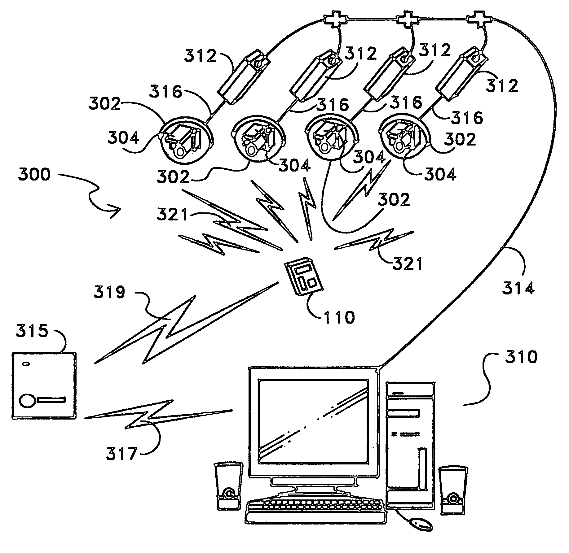
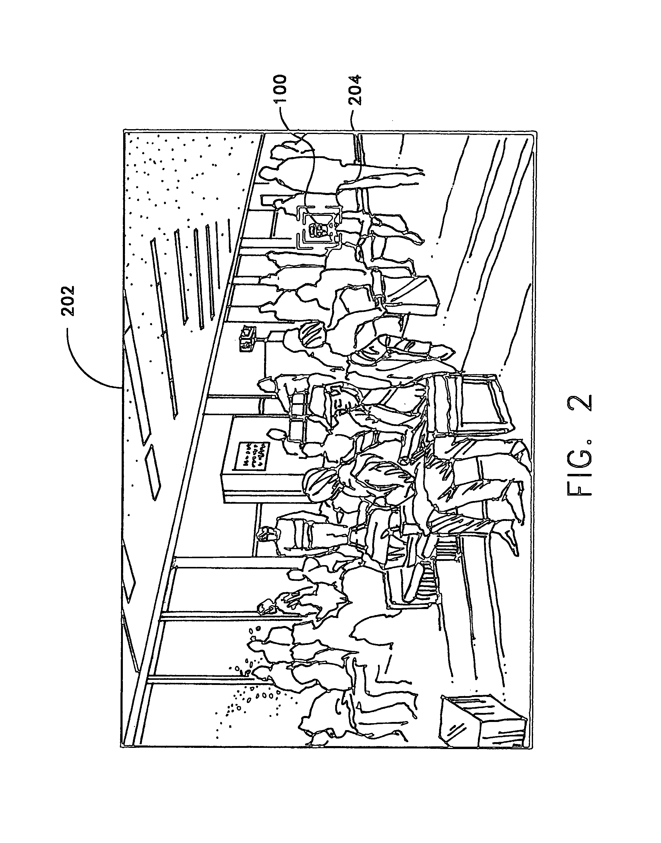
[0033]The disclosed systems and methods may be employed to RFID and / or visually track objects in a variety of different application environments, for example, in asset tracking applications. Other example environments in which the disclosed locating systems and methods may be implemented include, but are not limited to, tracking of personnel or other individuals. For example, one specific case is tracking passengers through an airport (or other passenger processing facility such as train station, passenger dock, etc.) in an exemplary manner as described below.

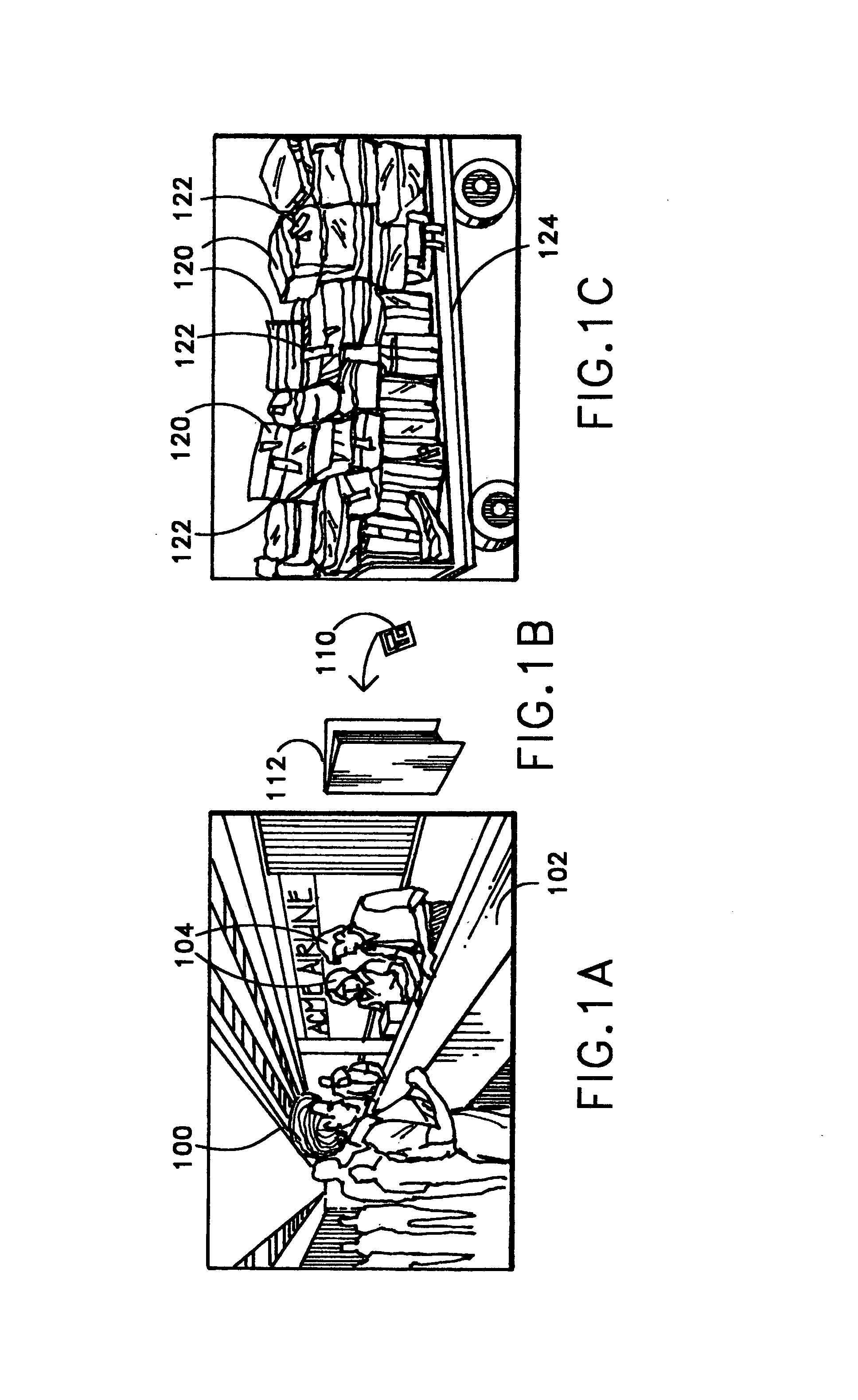
[0034]FIG. 1A illustrates a passenger 100 during the check-in process at an airport ticket counter 102. During such a check-in process, passenger 100 may receive ticket / boarding documents for a flight, and / or may optionally check luggage for the flight. Although FIG. 1A illustrates ticket counter personnel 104 assisting passenger 102 with ticket / boarding documents, it will be understood that the disclosed systems and methods ma...


PUM


Abstract

Systems and methods that may be employed to visually locate and/or track objects equipped with active RFID tags. The disclosed systems and methods may employ an articulated camera/s, such as closed circuit television (“CCTV”) or other suitable type of articulated camera/s, that is equipped with an antenna array.

Description

[0001]This patent application claims priority to copending U.S. Provisional Patent Application Ser. No. 60 / 437,713, filed Jan. 2, 2003 , and entitled “SYSTEMS AND METHODS FOR LOCATION OF OBJECTS” by Washington, the entire disclosure of which is incorporated herein by reference.BACKGROUND OF THE INVENTION[0002]The present invention relates generally to systems and methods for locating objects, and in one exemplary application to asset locating systems.[0003]Active Radio Frequency Identification (“RFID”) is presently in use today to locate assets. These assets are typically critical use or expensive items that are otherwise difficult or labor intensive to locate. Examples of RFID applications include location of assets in crowded factory environments, location of shipping containers and updating the location of a shipping container as the container is moved past different fixed RFID receiver stations, and location of critical medical equipment.[0004]Existing RFID systems typically inc...

Claims


Application Information

Patent Timeline
Patent Type & Authority Patents(United States)
IPC IPC(8): G08B13/14G08B13/196
CPCG06K7/10079G08B13/19608G08B13/1963G08B13/19656G08B13/19693G08B13/19697G08B13/2462
Inventor WASHINGTON, RICHARD G.
Owner UTC FIRE & SECURITY AMERICAS CORPORATION INC
Why Eureka
Try Eureka