Antenna configuration and radar device including same

a technology of antenna array and configuration, applied in the field of antenna array, can solve the problems of inaccurate detection result, inability to sample accurate signal level, inability to achieve accurate detection results, etc., and achieve the effect of enhancing the degree of freedom of modulation inclination

Active Publication Date: 2006-12-19
DENSO CORP
View PDF6 Cites 42 Cited by
  • Summary
  • Abstract
  • Description
  • Claims
  • Application Information

AI Technical Summary

Benefits of technology

[0037]More particularly, according to the present invention, as described above, the sampling interval per channel can be shortened and then the modulation inclination can be sharply set as compared with the conventional device, so that the degree of freedom of the modulation inclination can be enhanced. Therefore, according to the present invention, for example when the beat signal based on reflection wave to be detected and the beat signal based on reflection wave which is not required to be detected are overlapped with each other in frequency, the frequencies of both the beat signals are controlled by varying the modulation inclination, whereby both the beat signals can be separated. Therefore, the beat signal based on the reflection wave to be detected can be surely extracted.

Problems solved by technology

Therefore, it is erroneously detected that the target exists within the detection range.
However, when an antialiasing filter is used when the reception signals from the plural channels are subjected to the time division processing by the mixer, an accurate detection result can not be achieved.
However, the antialiasing filter described above also removes information necessary to separate the multiplexed signals of the respective channels from one another, so that the signals of the respective channels are superposed on one another and an accurate signal level cannot be sampled.
Therefore, the sampling interval per channel and the sweeping time T when the frequency of the transmission signal is modulated are lengthened, so that the problem caused by aliasing described above is more liable to occur and also the detectable area of the relative speed is narrowed.

Method used


Image

  • Antenna configuration and radar device including same
  • Antenna configuration and radar device including same
  • Antenna configuration and radar device including same

Examples


first embodiment

[First Embodiment]

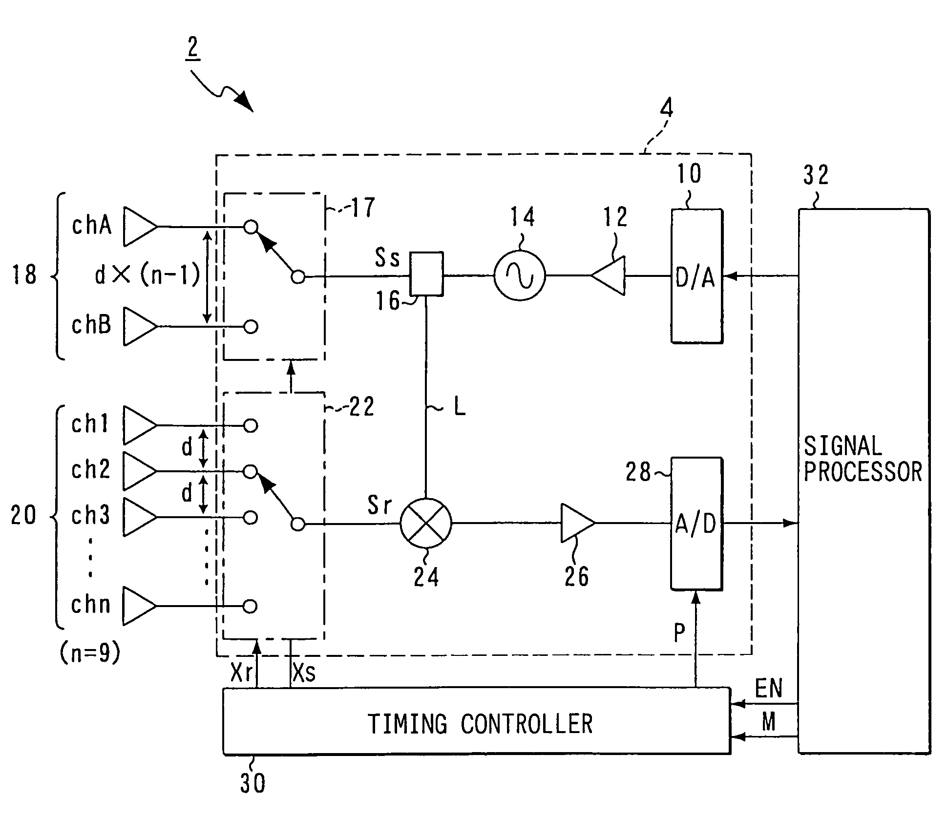
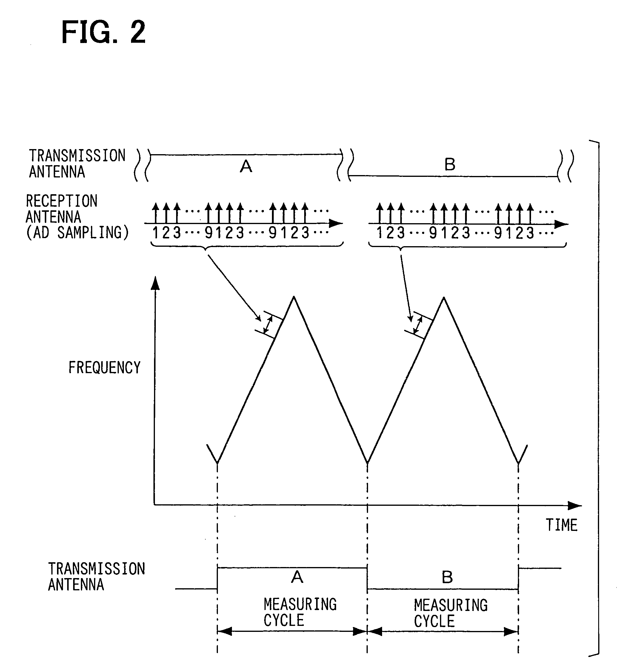
[0048]FIG. 1 is a block diagram showing the overall construction of a vehicle-mount type radar device according to this embodiment.

[0049]As shown in FIG. 1, a radar device 2 according to this embodiment includes a transceiver 4. The transceiver 4 includes a D / A converter 10 for generating a modulation signal having a triangular waveform in response to a modulation instruction, a voltage controlled oscillator (VCO) 14 to which the modulation signal generated in the D / A converter 10 is applied through a buffer 12 so that the oscillation frequency thereof is varied in conformity with the modulation signal, a divider 16 for dividing the output power of the VCO 14 into a transmission signal Ss and a local signal L, a transmission-side antenna portion 18 comprising transmission antennas of m (in this embodiment, m=2) for emitting radar waves corresponding to the transmission signal Ss, and a transmission switch 17 for alternatively selecting any one of the m transmission...


PUM


Abstract

A radar device (2) includes plural transmission antennas and plural reception antennas. The reception antennas constitute a reception-side antenna portion (20) and are arranged at an interval of d. The transmission antennas constitute a transmission-side antenna portion (18) and are arranged at an interval of d′=d×(n−1). The path length at which the electric wave is reflected from a target is identical between channels A9 and B1, and seventeen kinds of channels (A1 to A8, A9 or B1, B2 to B9) which are different in path length by every fixed distance are achieved. The data of the channels (A1 to A9 and B1 to B9) using different transmission antennas are respectively collected in different measuring cycles, and an error based on the time difference between the measuring cycles is corrected on the basis of a correction value calculated from the data of the channels A9, B1.

Description

CROSS REFERENCE TO RELATED APPLICATIONS[0001]This application is based upon, claims the benefit of priority of, and incorporates by reference the contents of Japanese Patent Application No. 2003-32708 filed on Feb. 10, 2003.FIELD OF THE INVENTION[0002]The present invention relates to a radar device for determining the direction to a target reflecting electric wave by transmitting and receiving an electric wave from a plurality of antennas, and a method of arranging the plurality of antennas.BACKGROUND OF THE INVENTION[0003]Radar devices have been used as safety apparatuses in vehicles for avoiding collisions. One of these radar devices in particular is the Frequency Modulated Continuous Wave (FMCW) radar device. The FMCW radar device can detect the distance to and relative speed of a target at the same time and is suitable for miniaturization and low-cost design due to its simple construction.[0004]In operation of the FMCW radar device, a transmission signal Ss is frequency modulate...

Claims


Application Information

Patent Timeline
Patent Type & Authority Patents(United States)
IPC IPC(8): G01S13/06G01S7/40H01Q21/06G01S13/93H01Q1/32G01S7/02G01S13/34H01Q3/24
CPCG01S13/343H01Q3/24
Inventor NATSUME, KAZUMAHAZUMI, HIROSHI
Owner DENSO CORP
Why Eureka
Try Eureka