Antenna system and RF signal interference abatement method

an antenna system and antenna technology, applied in the field of antenna system and rf signal interference abatement method, can solve the problems of array antenna system, high risk of interference by signals, intentional or unintentional interference,

Inactive Publication Date: 2006-12-19
HRL LAB
View PDF26 Cites 139 Cited by
  • Summary
  • Abstract
  • Description
  • Claims
  • Application Information

AI Technical Summary

Benefits of technology

[0017]Briefly and in general terms, this invention provides a multiple beam antenna system for robust GPS reception. This antenna system incorporates a spherical lens, and individual receiving antenna elements at the focal surface of the lens so that the GPS signal coming from an arbitrary direction is focused onto a small spot on the focusing surface of the lens that contains one or more receiving elements. Each receiving element contains switches and impedance matching circuits so that the element can be switched off and the signal can be routed into a matched load when interference is present. From the receiving elements, the GPS signal is routed to a GPS receiver after being combined with the GPS signals coming from other directions.
[0018]In another aspect, this invention provides a method for reducing potential interference to a GPS receiver by using a tiered GPS system with unmanned air vehicles (UAVs) serving as a secondary GPS position and timing reference constellation. Each UAV receives GPS signals from the GPS satellite constellation, and from this information fixes the UAV's absolute location. This information is retransmitted to the terrestrial GPS receiver in a spread-spectrum manner similar to the method currently used for direct space reception. The retransmitted information can, if desired, be modulated onto a microwave carrier at a specified frequency.

Problems solved by technology

Because the carrier frequencies reside in an increasingly crowded band and the strength of the signal is so small, the GPS system is highly susceptible to interfering signals, intentionally or unintentionally directed toward the GPS receiver.
These phased array antenna systems require additional circuitry and complex algorithms to phase the elements of the array correctly and to track the jammers and / or the satellites.

Method used


Image

  • Antenna system and RF signal interference abatement method
  • Antenna system and RF signal interference abatement method
  • Antenna system and RF signal interference abatement method

Examples


Embodiment Construction

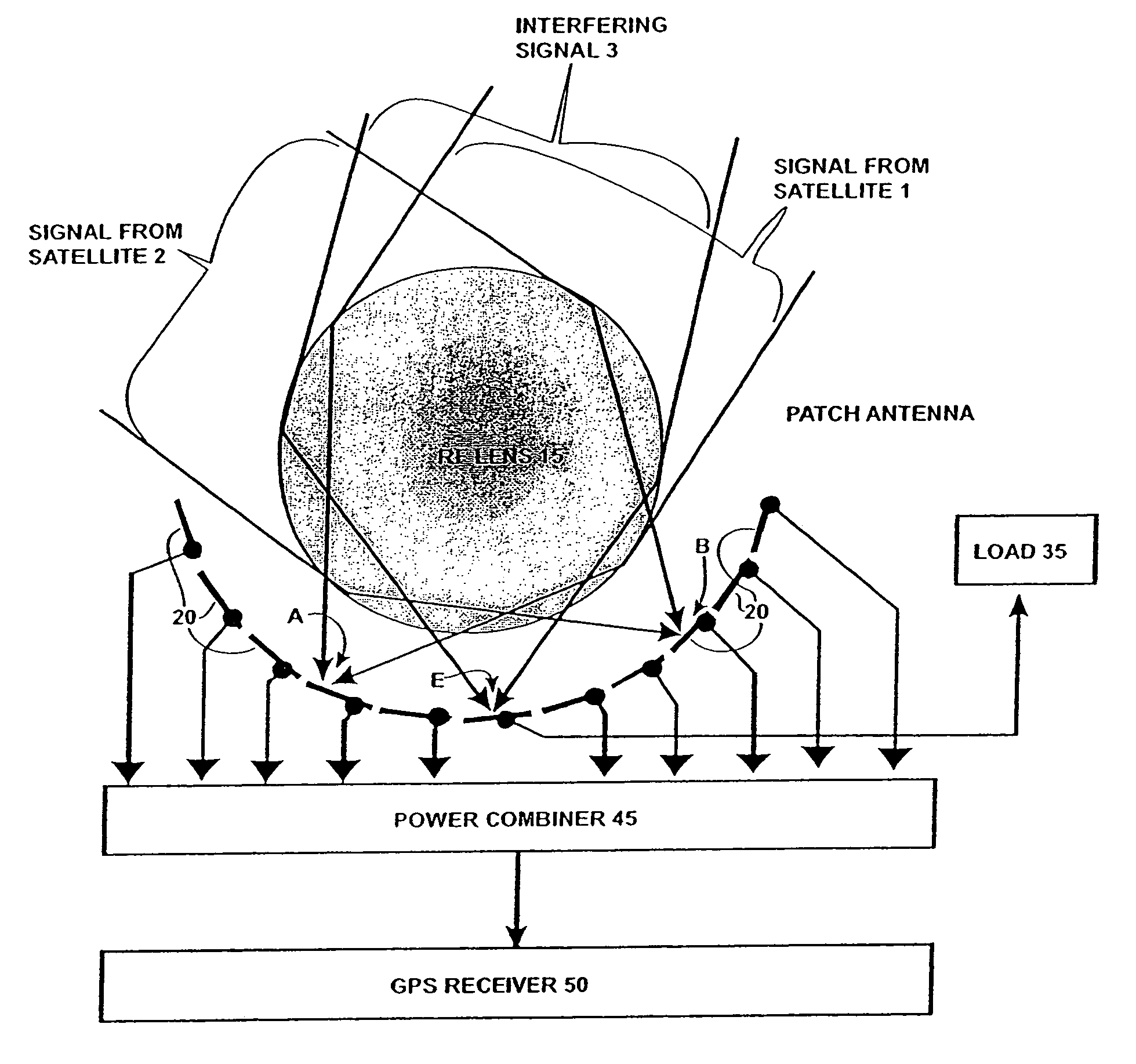
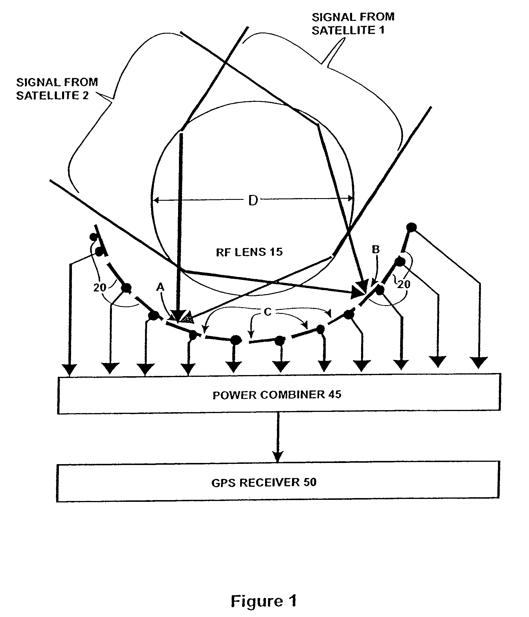
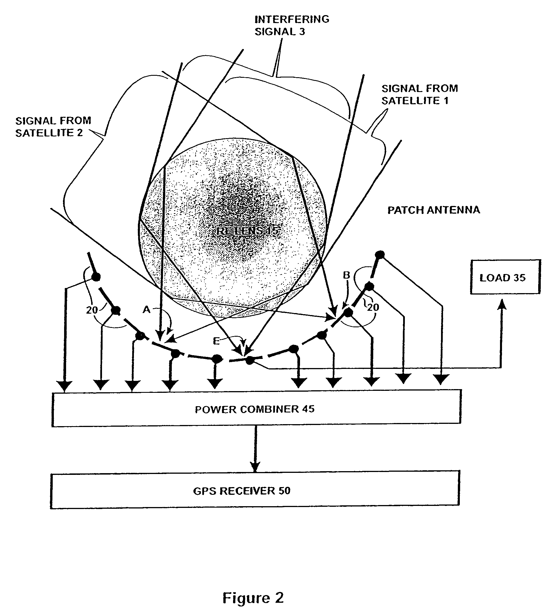
[0030]Today, military and non-military reliance on the Global Positioning System (GPS) for normal operations (not to mention emergencies) is nearly universal. The GPS system relies on a fixed number of satellites (for example the NAVSTAR constellation is composed of 24 satellites), from which a GPS receiver must acquire the signal from at least four to determine position and time. A set of GPS codes are broadcast from each satellite, the L2 coarse / acquisition code carrier is at 1227.6 MHz and the L1 precise code carrier is at 1575.42 MHz. Each frequency band is only a few MHz, although the receiver must be capable of providing a frequency offset of approximately 10 MHz to account for the Doppler effect of the satellites' motions. Spread-spectrum techniques are use to modulate each carrier with location and timing information, thus the carrier is spread as pseudo-noise across each band. Omni-directional antennas can then be used to receive signals from all of the visible satellites, ...


PUM


Abstract

Disclosed is an antenna system including a Luneberg Lens having a spherically shaped outer surface and a spherically shaped focal surface spaced from its outer surface with a plurality of patch antenna elements disposed along the focal surface of the Luneberg Lens; and a power combiner for combining signals received by said plurality of patch antenna elements. The disclosed antenna system may be used a part of a robust GPS system having a plurality of GPS satellites each transmitting a GPS signal; a plurality of airborne GPS platforms, each GPS platform including a GPS transmitter for transmitting its own GPS signal, the GPS signals being transmitted from the plurality of airborne GPS platforms being differentiated from the GPS signals transmitted by visible GPS satellites; and at least one terrestrially located GPS receiver for receiving the GPS signals transmitted by visible ones of the GPS satellites and by visible ones of said airborne GPS platforms.

Description

CROSS-REFERENCE TO RELATED APPLICATIONS[0001]This patent application is a divisional application of U.S. Ser. No. 10 / 154,580, filed on May 23, 2002, U.S. Pat. No. 6,867,741 which claims benefit of U.S. Provisional Application No. 60 / 316,665, filed on Aug. 30, 2001.TECHNICAL FIELD[0002]Invention relates to an antenna system and a method to insure reception of Radio Frequency (RF) signals, such as Global Positioning System (GPS) signals from satellites, even in the presence of intentional or unintentional interference.BACKGROUND OF THE INVENTION[0003]The global positioning system (GPS) presently in use utilizes two carrier frequencies, 1.227 GHz (the L2 band) and 1.575 GHz (the L1 band), to transmit spread-spectrum signals from space vehicles, i.e., GPS satellites, to GPS receivers. The spectral densities of the signals are very small, on the order of −160 dBW / Hz. Because the carrier frequencies reside in an increasingly crowded band and the strength of the signal is so small, the GPS...

Claims


Application Information

Patent Timeline
Patent Type & Authority Patents(United States)
IPC IPC(8): H01Q15/08H01Q19/06G01S1/00G01S5/00G01S19/44H01Q3/26H01Q5/00H01Q5/45H01Q9/04H01Q21/00
CPCH01Q5/45G01S19/215G01S19/23G01S19/36H01Q3/2611H01Q9/0428H01Q15/08H01Q19/06H01Q21/0031H04K3/228H04K3/255H04K3/90G01S19/11G01S5/0072H04K2203/22H04K2203/32G01S19/115
Inventor SCHAFFNER, JAMES H.LYNCH, JONATHAN J.SIEVENPIPER, DANIEL F.
Owner HRL LAB
Why Eureka
Try Eureka