Data transmission system, transmission method of optical network monitor control signal, and node

a data transmission system and monitor control technology, applied in the direction of multiplex communication, transmission monitoring, instruments, etc., can solve the problems of poor control network influence on the operation and maintenance of the signal network, fault of the signal network becomes exactly a fault of the monitor control network, and the external network is unsuitable for swift supervision/control, etc., to achieve the effect of keeping even more reliability, reducing transmission delay of monitor control signal, and reducing costs

Inactive Publication Date: 2006-12-19
KDDI CORP
View PDF1 Cites 18 Cited by
  • Summary
  • Abstract
  • Description
  • Claims
  • Application Information

AI Technical Summary

Benefits of technology

[0021]The above configuration makes it possible to switch over a signal network (a first network) and an external network (a second network)as the transmission path of the monitor control signal at low costs. Also, the signal network (the first network) transmits a monitor control signal in normal operation while the external network (the second network) transmits the monitor control signal when the signal network has a fault, and thus the system can keep even more reliability for the monitor control signal than that for the data signal. Transmission delay of a monitor control signal also becomes minimal. Moreover, it is not necessary to strengthen the reliability of the external network as much as that of the signal network and therefore the signal network can be monitored / controlled at low costs. Furthermore, since a monitor control signal is distributed by the signal distributor, a channel change in the signal network becomes easier. At the same time, continuity can be checked with a loop back test and a fault part can be cut off easily.

Problems solved by technology

A fault in the monitor control network gives a bad influence to the operation and maintenance of the signal network.
Therefore, such an external network is unsuitable for a swift supervision / control because not only it has a long delay time but also it is unstable.
On the other hand, when a signal network is used as the monitor control network, namely in a case that a monitor control signal is transmitted through a signal network, a fault of the signal network becomes exactly a fault of the monitor control network.
In such case, it is impossible to monitor and control the isolated nodes.
Generally, a monitor control signal is assigned one wavelength and therefore it also leads to the waste of resources.

Method used


Image

  • Data transmission system, transmission method of optical network monitor control signal, and node
  • Data transmission system, transmission method of optical network monitor control signal, and node
  • Data transmission system, transmission method of optical network monitor control signal, and node

Examples


Embodiment Construction

[0028]Embodiments of the invention are explained below in detail with reference to the drawings.

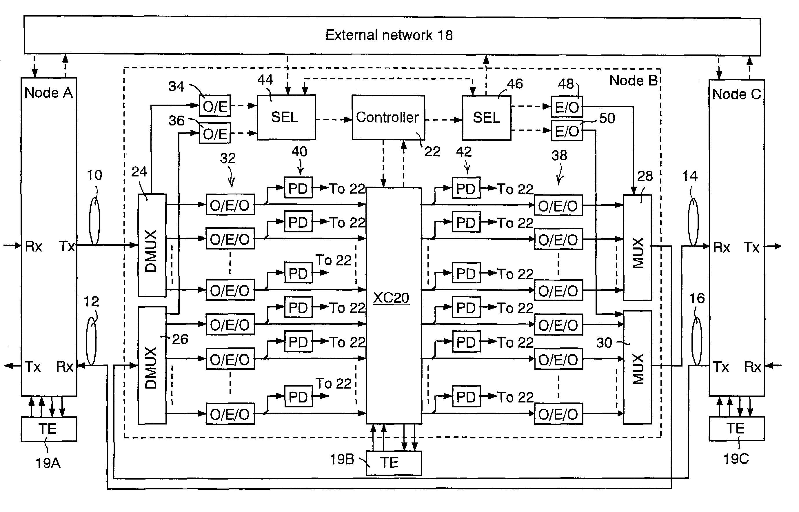
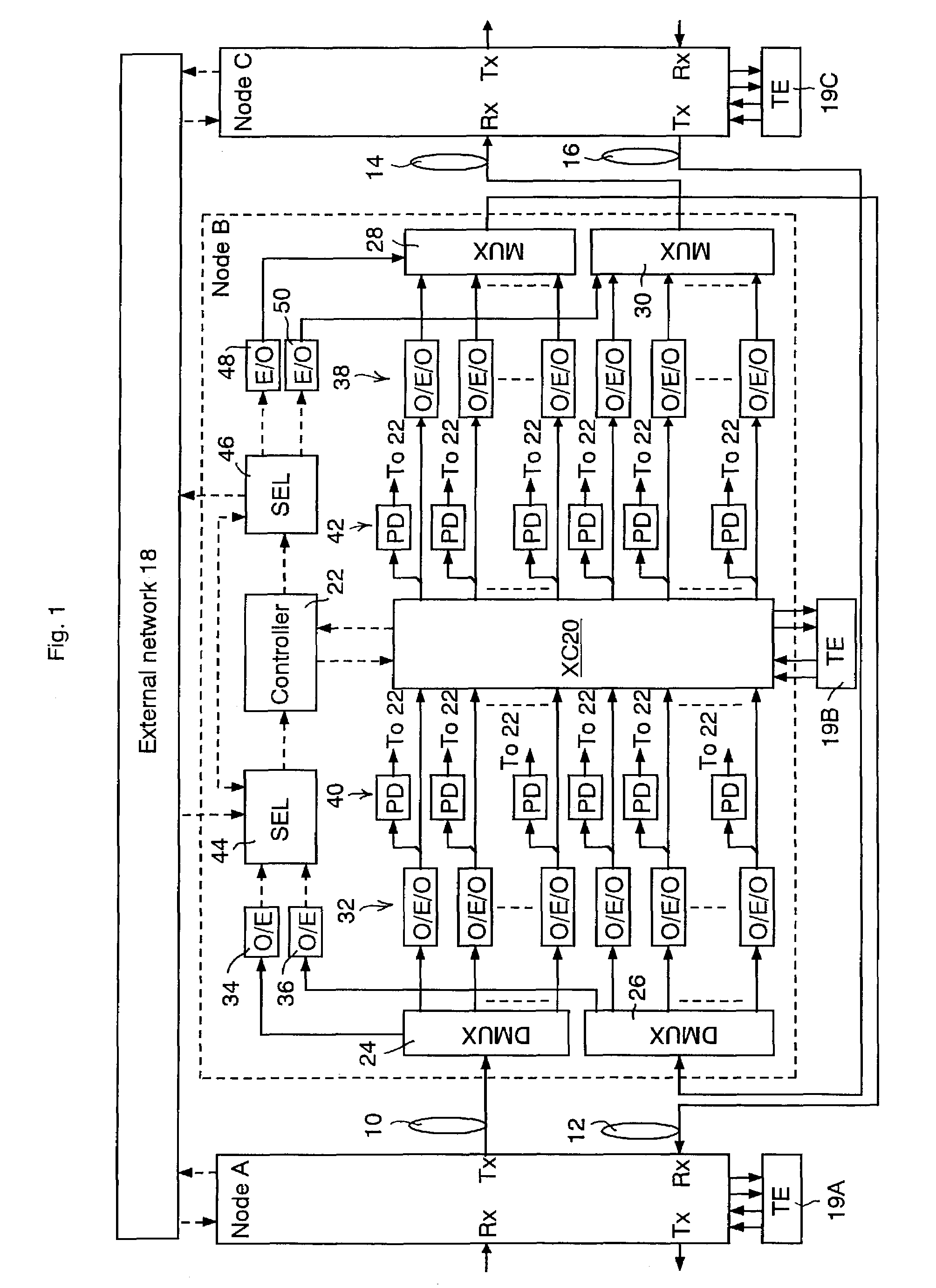
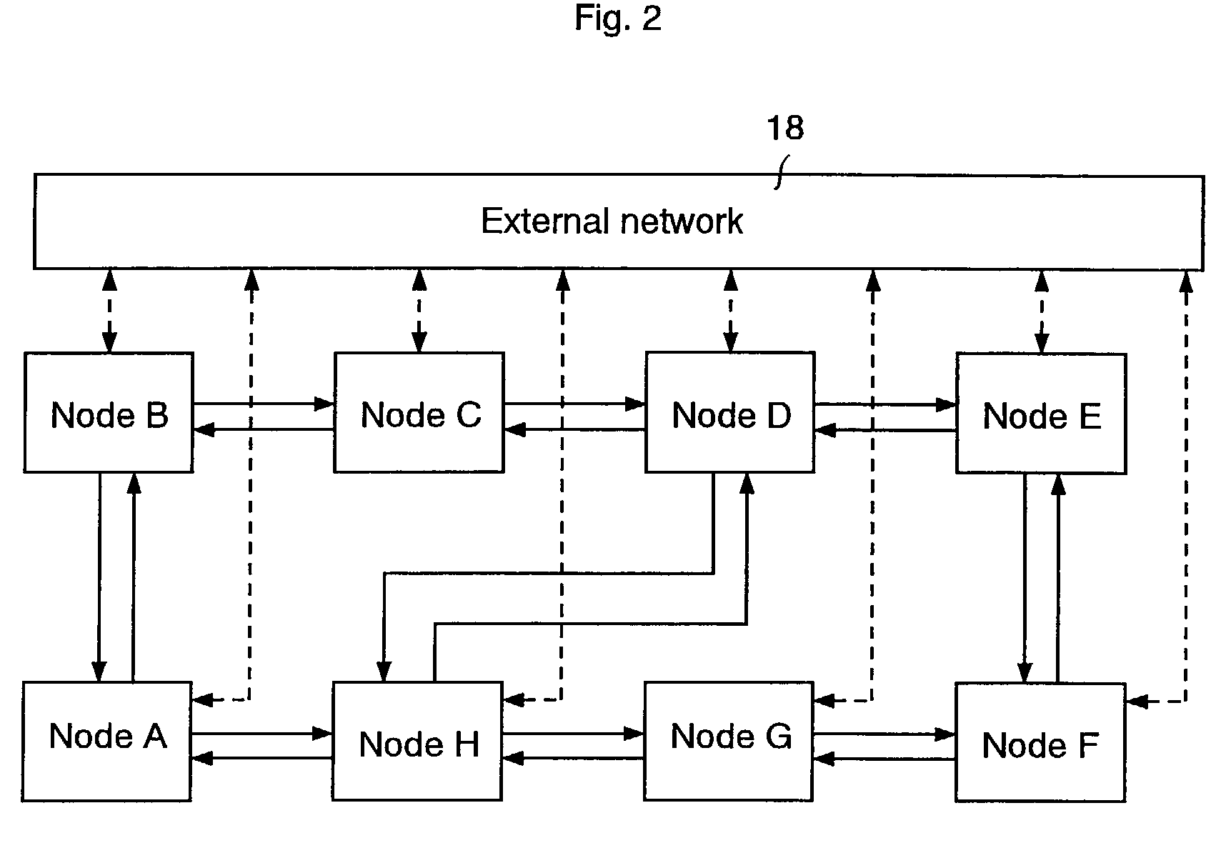
[0029]FIG. 1 shows a schematic block diagram of an embodiment according to the present invention, and FIG. 2 shows an example of network configurations according to the embodiment. In FIG. 1, a solid line with an arrow expresses an optical signal, and a broken line with an arrow expresses an electric signal. The example is shown on the assumption that nodes A, B, and C are connected on a ring or mesh type optical network in this order. That is, the node A connects to the node B through optical fibers 10 and 12, and the node B connects to the node C through optical fibers 14 and 16. The optical fibers 10, 12, 14, and 16 form optical transmission lines of a signal network. The nodes A, B, and C are all connected to an external network 18 which works as a spare monitor control network to transmit a monitor control signal when the signal network has a fault. Although the nodes A and C connect...


PUM


Abstract

To realize a highly reliable monitor control signal network at low costs, a data transmission system comprises a first network to optically transmit a data signal and a monitor control signal, first and second nodes connecting to the first network, and a second network capable of transmitting the monitor control signal. The first node comprises a demultiplexer to demultiplex the data signal and the monitor control signal out of the signal light from the first network, a signal distributor having a plurality of input ports and a plurality of output ports to distribute the data signal demultiplexed by the demultiplexer into designated output port, a controller to control the signal distributor and to monitor each part in the first node, a first selector to select one of the monitor control signal demultiplexed by the demultiplexer and the other monitor control signal entered from the second network and to apply the selected one to the controller, a second selector to output the monitor control signal output for the second node output from the controller toward one of the first network and the second networks, and a multiplexer to multiplex the monitor control signal output for the first network output from the second selector and the data signal output from the signal distributor and to output the multiplexed signals onto the first network.

Description

CROSS REFERENCE TO RELATED APPLICATIONS[0001]This application claims priority to Japanese Patent Application No. 2002-094478, filed Mar. 29, 2002, the entire contents of which are incorporated herein by reference.FIELD OF THE INVENTION[0002]This invention generally relates to a data transmission system, a transmission method of an optical network monitor control signal, and a node.BACKGROUND OF THE INVENTION[0003]In a large-scale network, a system to remotely monitor each node connecting to the network is indispensable.[0004]As a configuration to transmit a monitor signal, a control signal, and a status signal (generically referred to hereinafter as a “monitor control signal”) between a monitor center and each node, one typical type is to multiplex a monitor control signal on a network to transmit a data signal itself, hereinafter referred to as a “signal network”, and the other is to provide another external network besides the signal network to transmit a monitor control signal th...

Claims


Application Information

Patent Timeline
Patent Type & Authority Patents(United States)
IPC IPC(8): H04B14/02H04B10/03H04B1/74H04B10/038H04B10/07H04B10/077H04B10/27H04B10/291H04B17/00H04Q11/00
CPCH04Q11/0062H04Q11/0071H04Q2011/0069H04Q2011/0083
Inventor HAYASHI, MICHIAKIOTANI, TOMOHIROSUZUKI, MASATOSHI
Owner KDDI CORP
Why Eureka
Try Eureka