Powered tubing cutter

a tubing cutter and motor technology, applied in the field of hand-held, motor-powered tubing cutters, can solve the problems of uneven cutting, time-consuming, inaccurate pipe cutting method, etc., and achieve the effect of improving cutting precision

Inactive Publication Date: 2006-12-26
GREEN CARROLL D +1
View PDF17 Cites 32 Cited by
  • Summary
  • Abstract
  • Description
  • Claims
  • Application Information

AI Technical Summary

Benefits of technology

[0021]The powered tube cutter may also include a cover that fits over the chain drive. The chain drive cover also has a depth-measuring device, which comprises a rod that may be locked into place at a certain length. Once the rod is locked into place multiple cuts may be made at the same length without having to measure prior to each cut. Also, a polishing device may be secured to the drive plate so that ends of the tubes / pipes may be polished after they are cut.
[0022]Accordingly, it is a principal object of the invention to provide a portable, hand held pipe / tube cutter that will increase production speed for plumbers, electricians or others having to cut piping / tubing.
[0025]Still another object of the invention is to provide a pipe / tube cutter that has an integrated measuring device so that a number of pipes / tubes may be cut at the same length without having to measure after each cut to improve cutting precision.
[0026]It is an object of the invention to provide improved elements and arrangements thereof for the purposes described which is inexpensive, dependable and fully effective in accomplishing its intended purposes.

Problems solved by technology

This is very time consuming because each cut takes several minutes.
Another problem is that this method of cutting the pipes is very inaccurate because each pipe must be separately measured prior to cutting which will likely result in uneven cuts.

Method used


Image

  • Powered tubing cutter
  • Powered tubing cutter
  • Powered tubing cutter

Examples


Embodiment Construction

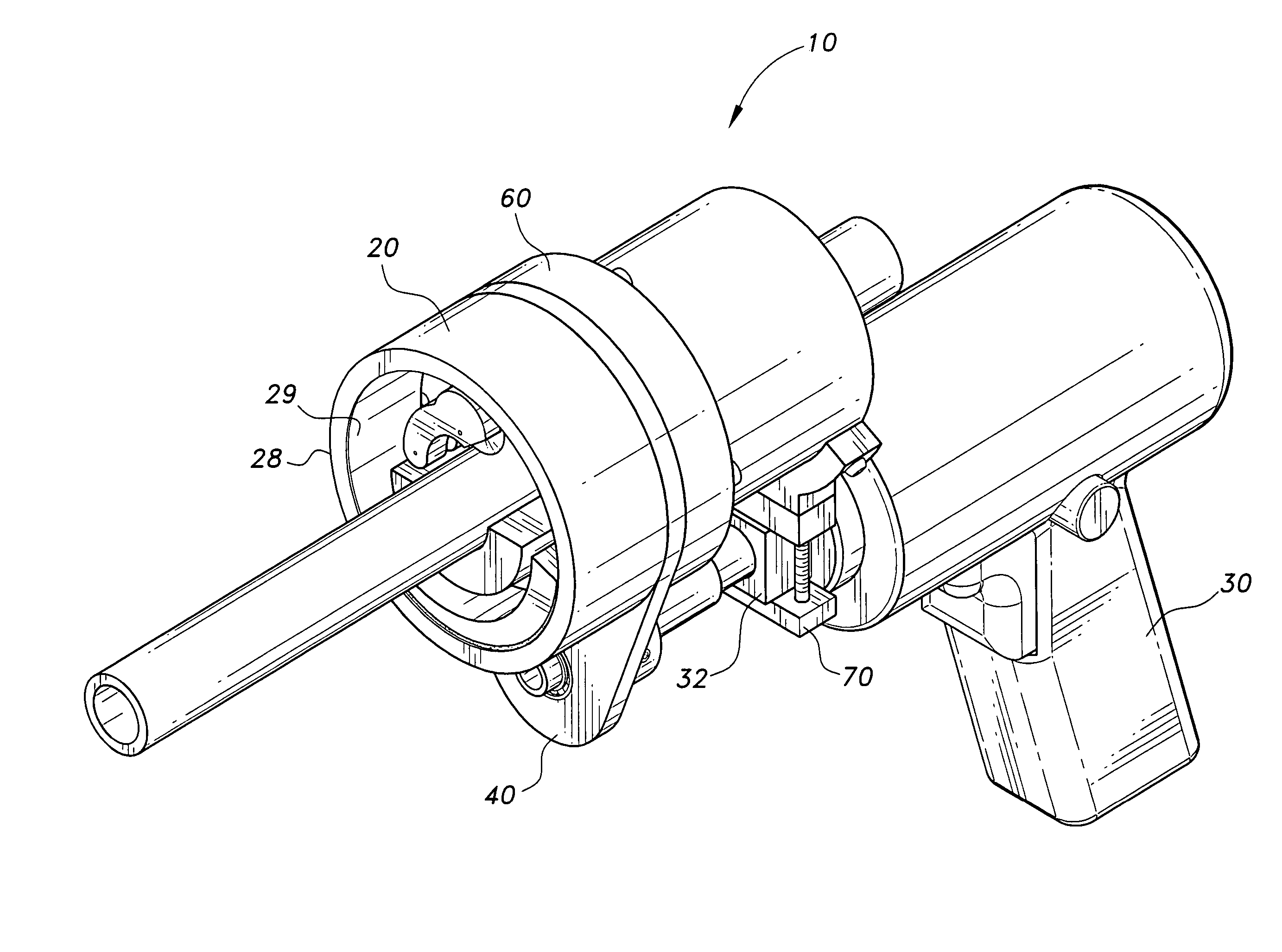
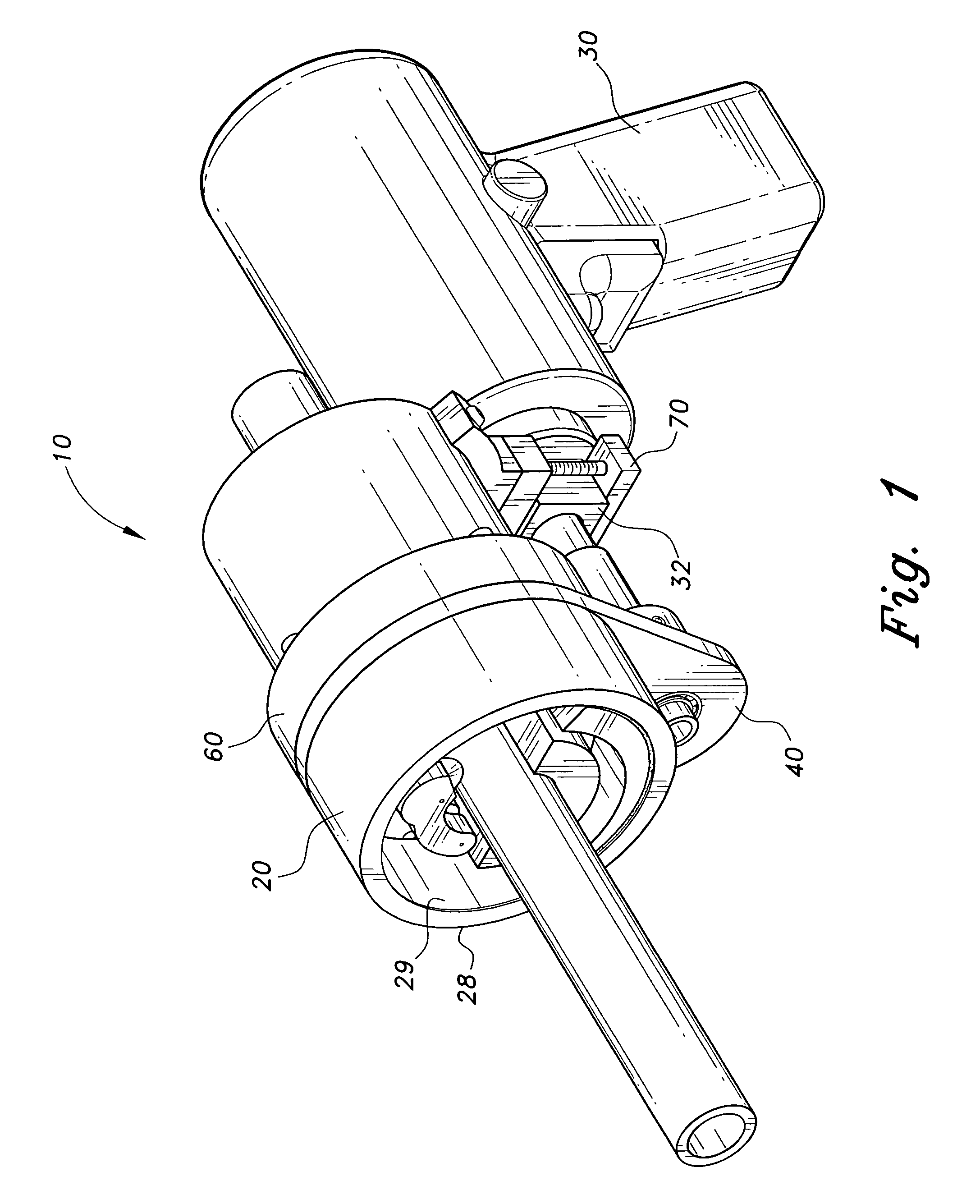
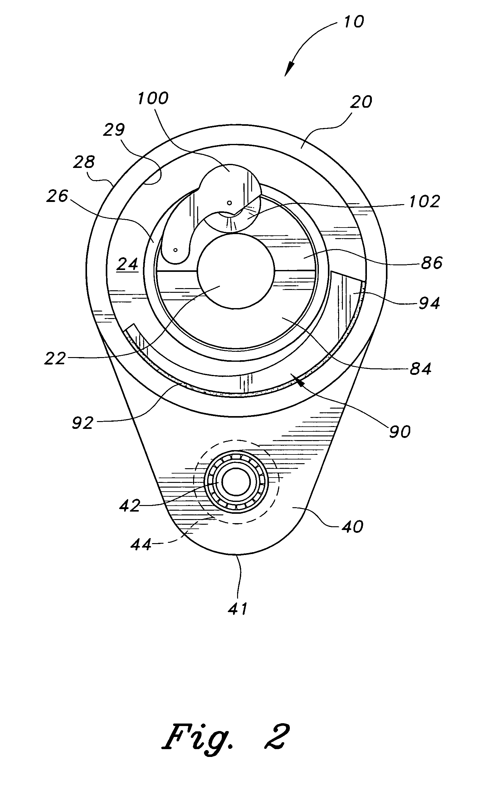
[0042]The present invention is a powered tubing cutter that improves the speed of production for plumbers, electricians and the like. The powered tubing cutter is a mechanical device that is driven by a motor to cut piping / tubing made from any material including, but not limited to, copper and steel. FIG. 1 is an environmental perspective view of the powered tubing cutter 10. The powered tubing cutter 10 generally comprises a housing cap 20, a hand held motor case 30, a drive plate 40, a drive 50, a rear cover 60, a mounting bracket 70, a cam plate 90 (shown in FIGS. 2 and 3) and a cutting assembly 100 (shown in FIGS. 2 and 3).

[0043]FIG. 3 is an exploded perspective view of the cutter 10 depicting each of the individual parts and their location in the cutter 10 in relation to one another. The motor case 30 is a housing that encloses the electric motor that powers the cutter 10. The case 30 has a main body portion and a handle portion 34 disposed along the bottom of the case 30. The ...


PUM

PropertyMeasurementUnit
inside radiusaaaaaaaaaa
thicknessaaaaaaaaaa
frictionaaaaaaaaaa

Abstract

The powered tubing cutter is a hand held, mechanical device driven by a motor for cutting tubing / piping. The device comprises a housing, a drive plate, a main drive shaft, a cutting assembly having a cutting blade, a cam plate and a chain drive secured to a motor housing, having a handle, by a mounting bracket. The chain drive is powered by the motor, which causes the main drive shaft to rotate. The cutting assembly is pivotally secured to a pin on the main drive shaft. The pipe / tube to be cut is placed into the hole in the center of the housing and the main drive shaft. As the cutting assembly rotates with the main drive shaft the cam plate forces the cutting blade into cutting engagement with the tube / pipe.

Description

CROSS-REFERENCE TO RELATED APPLICATION[0001]This application claims the benefit of U.S. Provisional Patent Application Ser. No. 60 / 510,524, filed Oct. 14, 2003.BACKGROUND OF THE INVENTION[0002]1. Field of the Invention[0003]The present invention relates to devices for cutting tubes and pipes, and more particularly to a hand held, motor powered tubing cutter that can be used to cut any length of pipe or tube.[0004]2. Description of the Related Art[0005]Plumbers, electricians, maintenance personnel and many other laborers often need to cut tubing or piping. Many times pipes or tubes are first run through the floor or a wall of a structure and then must be recut. For example, when plumbers put in baseboard heating the piping is run through the floor 1½ inches from the wall. Each one of the pipes then has to be recut. Conventionally, the plumber would recut the pipes by sitting on the floor with a small tubing cutter, measure each pipe and then cut each pipe. This is very time consuming...

Claims


Application Information

Patent Timeline
Patent Type & Authority Patents(United States)
IPC IPC(8): B26D3/16B26B27/00B23D21/04B26B25/00
CPCB23D21/04B26B25/00B23D21/08
Inventor GREEN, CARROLL D.SHERMAN, DUANE C.
Owner GREEN CARROLL D
Why Eureka
Try Eureka