[0007]Accordingly, at the beginning of a steering process an outflow of the
hydraulic fluid, which is supplied by the steering unit, through the pilot pressure valve is possible. Thus, delays are avoided. At the same time, it becomes possible to use the
hydraulic fluid, which is supplied by the steering unit, for controlling the slide (or another valve element) of the steering valve. This is an
advantage, when the steering unit is also used as an emergency steering pump, so that during a failure of the pump, which supplies the pressure at the high-pressure connection, reliable steering of the vehicle is still possible. In the
normal state, a control device then activates the steering valve, for example by means of electromagnets. The use of the pilot pressure valve, avoids the situation wherein the pressures, which are supplied by the steering unit, superpose the pressures from the control device. The pilot
oil supply is located on the primary side, which causes a reduced pressure drop in relation to a
system, in which the pilot
oil supply is located on the
secondary side. In such a
system, a relatively large amount of oil had to be lifted to the
pressure level, which was also needed in the pilot
oil supply. This led to oversteering of the steering valve, which again caused an undesired occurrence of jerk. Locating the pilot oil supply on the primary side reduces this problem.
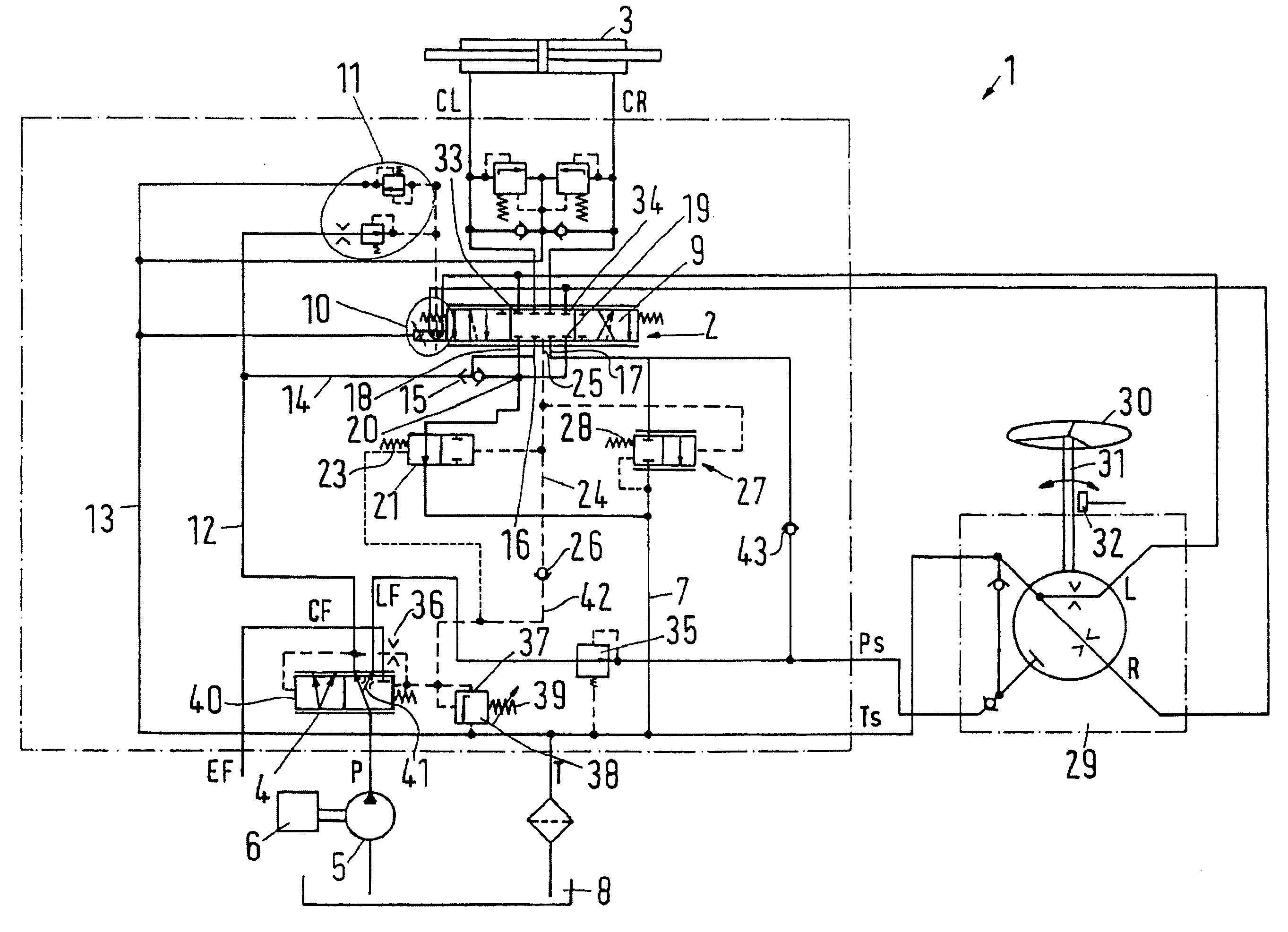
[0013]It is preferred that between the braking valve and the steering valve an emergency steering line branches off, which is connected with a pressure inlet of the steering unit via a non-return
valve opening in the direction of the steering unit. In this case, the steering valve can, in an improved manner, be used for an emergency steering. As long as the pressure at the pressure inlet of the steering unit is larger than the pressure at the steering valve, the non-return valve is closed. When, however, the pressure at the pressure inlet of the steering unit drops, for example because the supply via the pump fails, the steering valve can supply sufficient
hydraulic fluid via the non-return valve to initiate the emergency steering of the vehicle.
[0014]Preferably, the high-pressure connection is connected with an
overpressure valve, which is connected with the low-pressure connection. Together with the pilot pressure valve, this
overpressure valve enables an endstop function. When the steering motor is taken to an end position, the pressure at the high-pressure connection could increase so much that the steering motor is damaged. In the first line, the
overpressure valve limits the size of this pressure. At the same time, however, the pressure in the load-
sensing system also increases. The pressure in the load-
sensing system then gets at least as large as the pressure at the high-pressure connection. Together with the force of the spring, the pressure in the load-
sensing system is then sufficient to close the pilot pressure valve. Thus, however, it is prevented that hydraulic fluid from the steering unit can flow off via the pilot pressure valve. The hydraulic fluid trapped in the steering unit then signals to the driver, that the steering motor is in the end position. A further turning of the steering handwheel is thus, in a manner of speaking, mechanically prevented, without requiring the fitting of mechanical stops.
[0015]It is preferred that the high-pressure connection is connected with the overpressure valve via the load-sensing system. Basically, no large amount of hydraulic fluid has to be discharged. Therefore, it is sufficient to use the comparatively small cross-sections of the available load-sensing system for the
pressure reduction. This keeps the manufacturing costs low.
[0016]Preferably, a non-return
valve opening in the direction of the pilot pressure valve is located in a load-sensing
pipe between the high-pressure connection and the pilot pressure valve. On the one hand, this non-return valve enables the pressure from the high-pressure connection to reach the pilot pressure valve. However, it prevents an increased load pressure, which occurs in the steering valve, for example generated by negative loads, from getting through to the pump, which supplies the pressure to the high-pressure connection.
[0017]Preferably, a priority valve is located between the high-pressure connection and the steering valve, said priority valve having a position indication. In many cases, a priority valve is used not only for supplying the steering of a vehicle, but also other consumers, with hydraulic fluid. The priority valve then ensures that, when the steering needs hydraulic fluid, this is primarily supplied to the steering. The remaining hydraulic consumers are then, at least temporarily, out of operation. The position indication now provides the priority valve with an additional property: the driver is informed that the available amount of the supplied hydraulic fluid is no longer sufficient for the supply of additional consumers. He thus learns that the hydraulic supply is approaching its
capacity limit. In this case, the driver knows that he must anticipate that the steering will work more slowly than in a case, where the full capacity of the hydraulic supply is available. The driver can adapt his steering behaviour accordingly and, for example, slow down his steering movements.

