
In-situ casting of well equipment

a technology of insitu casting and well equipment, which is applied in the direction of insulation, sealing/packing, borehole/well accessories, etc., can solve the problems of cement or other solidifying substance shrinkage during solidification or curing

Inactive Publication Date: 2006-12-26
SHELL USA INC
View PDF11 Cites 116 Cited by
  • Summary
  • Abstract
  • Description
  • Claims
  • Application Information

AI Technical Summary

Benefits of technology

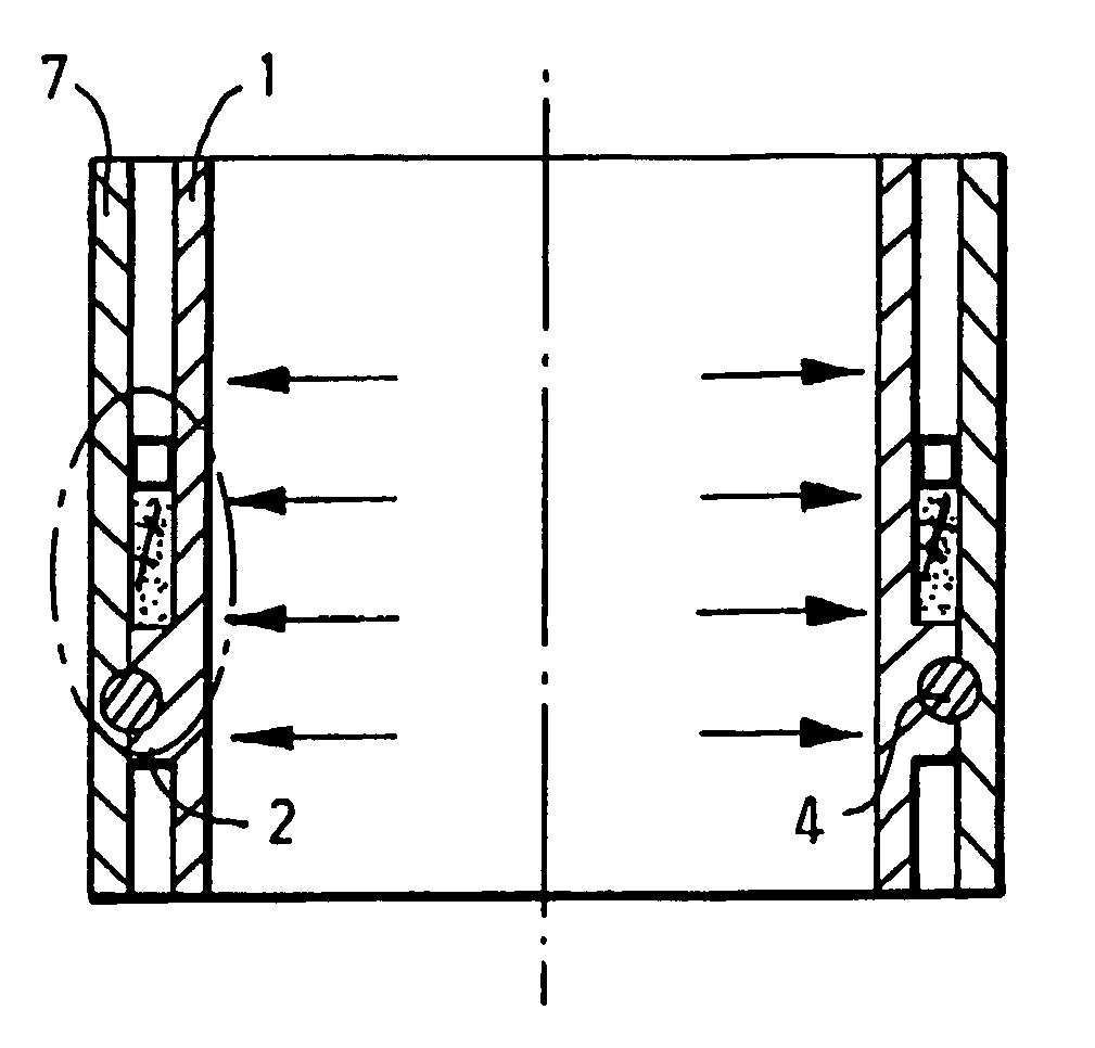
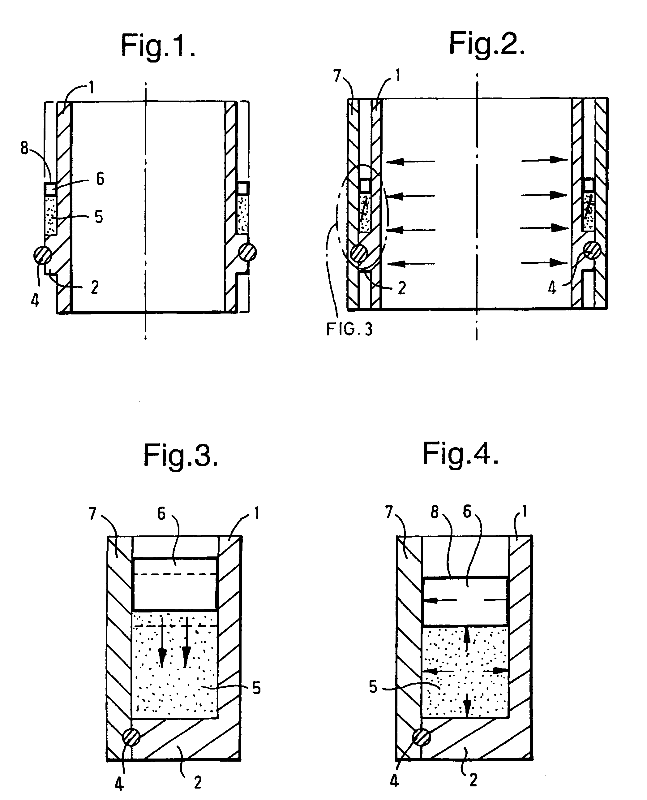
The invention provides a method for in-situ casting well equipment using an expanding alloy. The alloy is placed in a cavity in the well and heated to a temperature above its melting point. The alloy is then cooled down to its ambient well temperature and solidifies and expands within the cavity. The alloy can be a Bismuth alloy, Gallium alloy, Antimony alloy, or an alloy of these metals. The method can be used to seal the cavities within well tubulars, the annuli between co-axial well tubulars, or any small gap or orifice within the well or surrounding formation. The technical effect of the invention is to provide a reliable and effective method for in-situ casting well equipment.

Problems solved by technology

A disadvantage of this and many other in-situ casting techniques is that the cement or other solidifying substance shrinks during solidification or curing as a result of higher atomic packing due to hydration and / or phase changes.

Method used


Image

  • In-situ casting of well equipment
  • In-situ casting of well equipment

Examples


Embodiment Construction

[0061]1) An experiment was carried out to verify that the expansion behaviour of Bismuth alloys is not limited to atmospheric conditions. A Bi58Sn42 (Bismuth-Tin) alloy was solidified in a pressurized chamber at 400 bar pressure. The pressurized chamber formed part of an experimental device which is described in SPE paper 64762 (“Improved Experimental Characterization of Cement / Rubber Zonal Isolation Materials”, authors M G Bosma, E K Cornelissen and A Schwing). The experiment indicated that under the test conditions the alloy expanded by 1.41% by volume.[0062]2) Another sample of a Bi58Sn42 alloy was cast into a dirty (i.e. coated with API Pipe Dope) piece of a tubular with an internal diameter of 37.5 cm and subsequently allowed to be solidified into a plug having a length of 104.6 mm within the tubular to test the sealing ability of the alloy. Water pressure was applied to the tubular section at one end of the solidified plug and the differential pressure was measured across the ...


PUM

PropertyMeasurementUnit
melting pointaaaaaaaaaa

Abstract

A method is provided of in-situ casting well equipment wherein a metal is used which expands upon solidification. A body of such metal is placed in a cavity in a well. Before or after placing the metal in the cavity in the well, the body is brought at a temperature above the melting point of the metal. The metal of the body in the cavity is solidified by cooling it down to below the melting point of the metal.

Description

FIELD OF THE INVENTION[0001]The invention relates to a method for in-situ casting of well equipment.BACKGROUND OF THE INVENTION[0002]It is standard practice to cast cement linings around well casings to create a fluid tight seal between the well interior and surrounding formation.[0003]A disadvantage of this and many other in-situ casting techniques is that the cement or other solidifying substance shrinks during solidification or curing as a result of higher atomic packing due to hydration and / or phase changes.SUMMARY OF THE INVENTION[0004]In accordance with one aspect of the invention, there is provided a method of in-situ casting well equipment wherein a metal is used which expands upon solidification, the method comprising the steps of:[0005]placing a body of said metal in a cavity in a well;[0006]bringing said body at a temperature above the melting point of the metal; and[0007]cooling down said body to below the melting point of the metal, thereby solidifying the metal of said...

Claims


Application Information

Patent Timeline
Patent Type & Authority Patents(United States)
IPC IPC(8): B22D19/04B22D23/06E21B33/13E21B29/10E21B36/00E21B41/00E21B43/10
CPCE21B29/10E21B33/13E21B36/00E21B43/103E21B43/106
Inventor BOSMA, MARTIN GERARD RENECORNELISSEN, ERIK KERSTDIMITRIADIS, KLISTHENISPETERS, MIKEWORRALL, ROBERT NICHOLAS
Owner SHELL USA INC
Learn More