
System and method for passive load attenuation in a wind turbine

a technology of wind turbines and passive load attenuation, which is applied in the field of wind turbines, can solve the problems of affecting not only the average wind load on the blades, the fatigue of the rotating blades, and the damage to the wind turbine blades

Active Publication Date: 2006-12-26
LM WIND POWER US TECH APS
View PDF6 Cites 50 Cited by
  • Summary
  • Abstract
  • Description
  • Claims
  • Application Information

AI Technical Summary

Benefits of technology

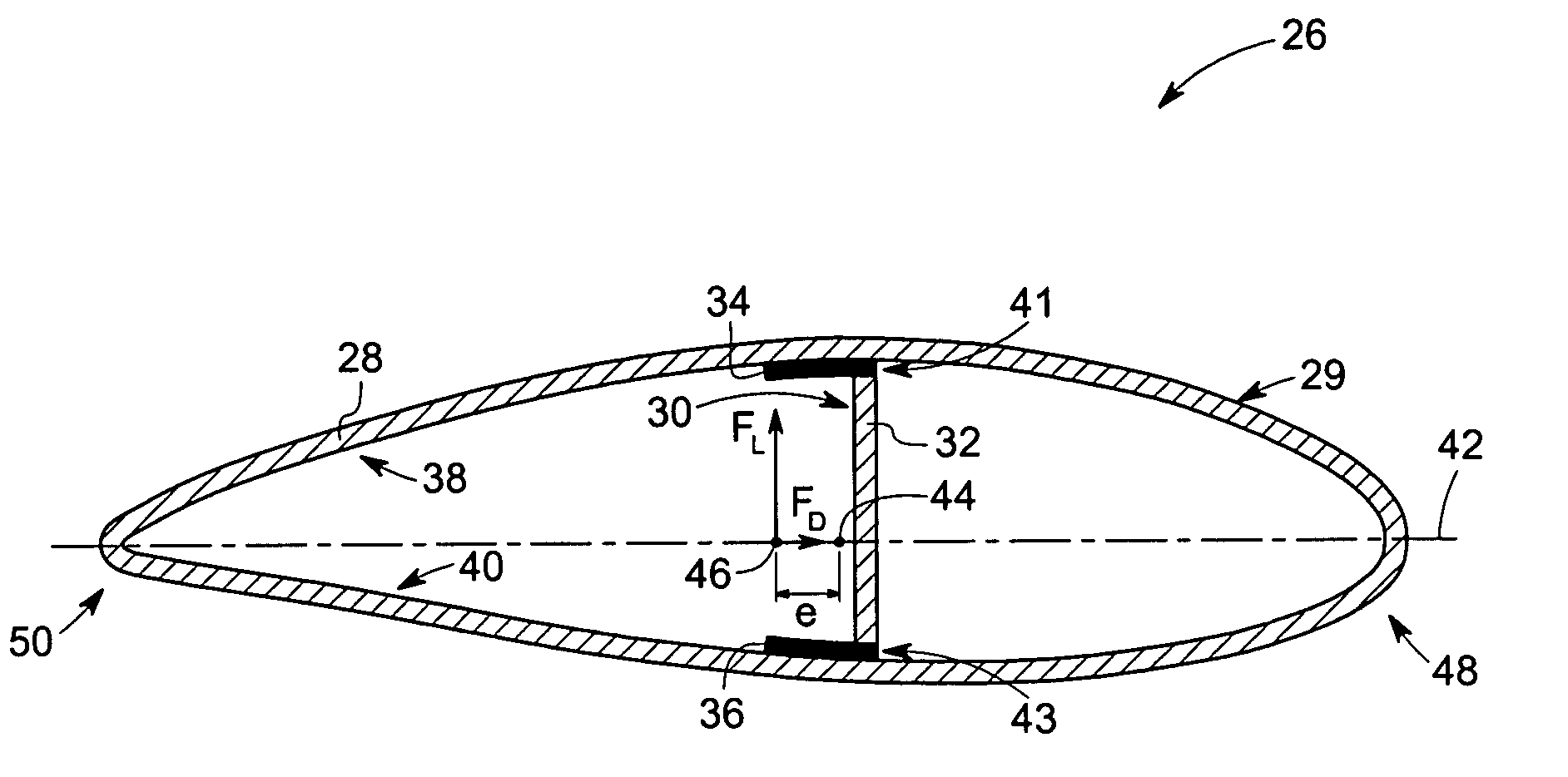
[0007]The present technique accordingly provides a novel approach to address the aforementioned problems. In one aspect, the present technique provides a wind turbine blade. The wind turbine blade includes an outer skin and an internal support structure. The skin has a closed airfoil shape and includes an outer surface, an inner surface, and opposite sides along a length of the blade. The internal support structure is disposed within the closed airfoil shape. The internal support structure includes at least one shear load bearing member disposed across the opposite sides and oriented lengthwise along the length of the blade. The internal support structure further includes a plurality of bending load bearing members disposed along the inner surface in a lengthwise direction along the length of the blade. The internal support structure is configured to position a shear center and a center of aerodynamic loading of the blade at different locations relative to one another. In another aspect, the present technique provides a wind turbine having a rotor including a plurality of blades as discussed above. In yet another aspect, the present technique provides a method for manufacturing a wind turbine blade as described above.

Problems solved by technology

Wind turbine blades often operate under atmospheric turbulence, resulting from disturbances in wind velocity.
Such disturbances subject the wind turbine blades to aerodynamic bending and shear loads, which result in fatigue of the rotating blades.
At times, these loads can be relatively high and damaging to the wind turbine blades.
When pitch changes are sufficiently rapid, they can affect not only the average wind load on the blades, but also vibratory loads influencing fatigue life throughout the system.
Unfortunately, this biased fiber lay-up material consumes additional material for the same load carrying capability of the blade.
This increased material consumption is due to the angled orientation of the fibers, which are no longer oriented with the load.
Accordingly, the blades are heavier and more costly to manufacture.

Method used


Image

  • System and method for passive load attenuation in a wind turbine
  • System and method for passive load attenuation in a wind turbine
  • System and method for passive load attenuation in a wind turbine

Examples


Embodiment Construction

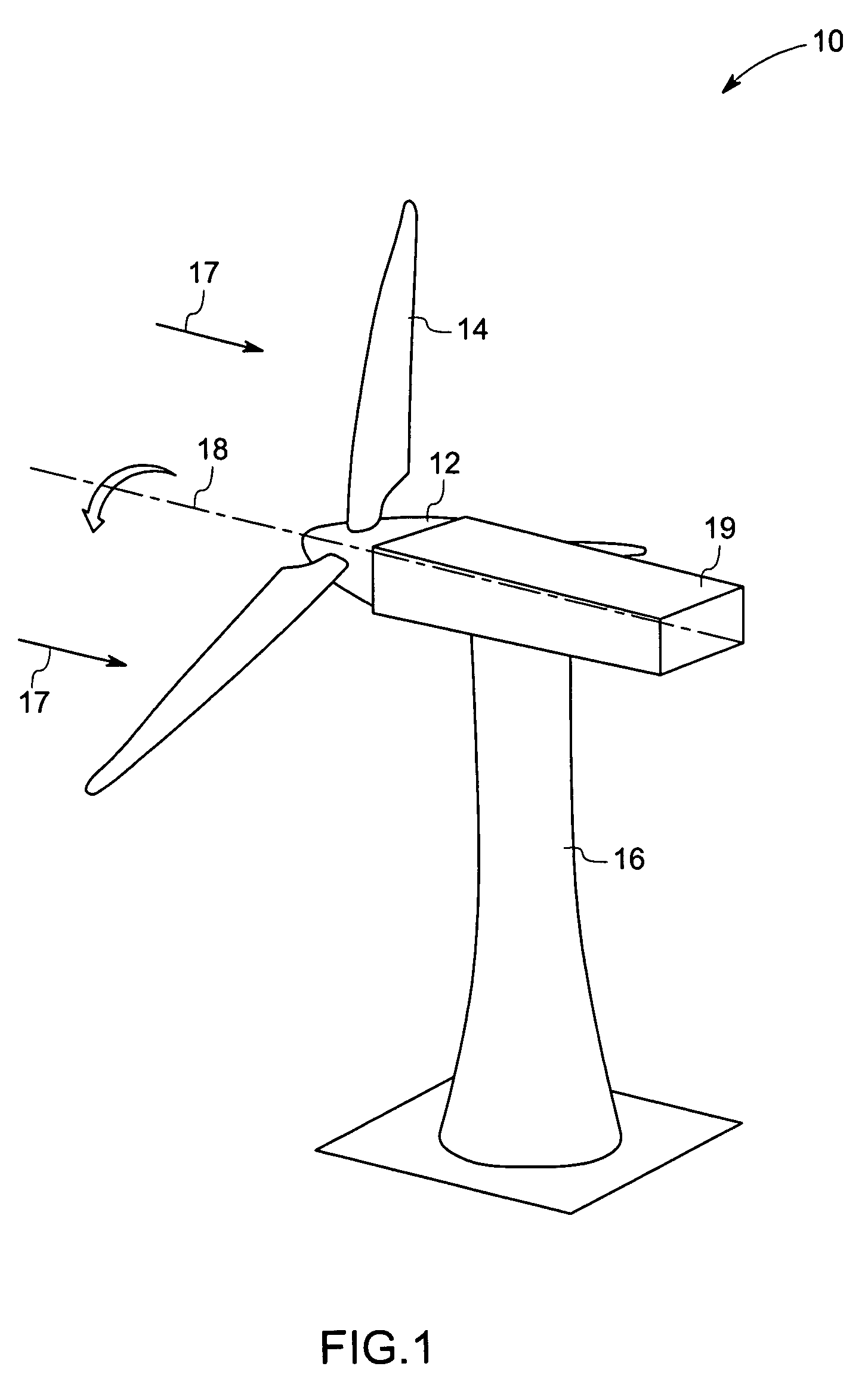
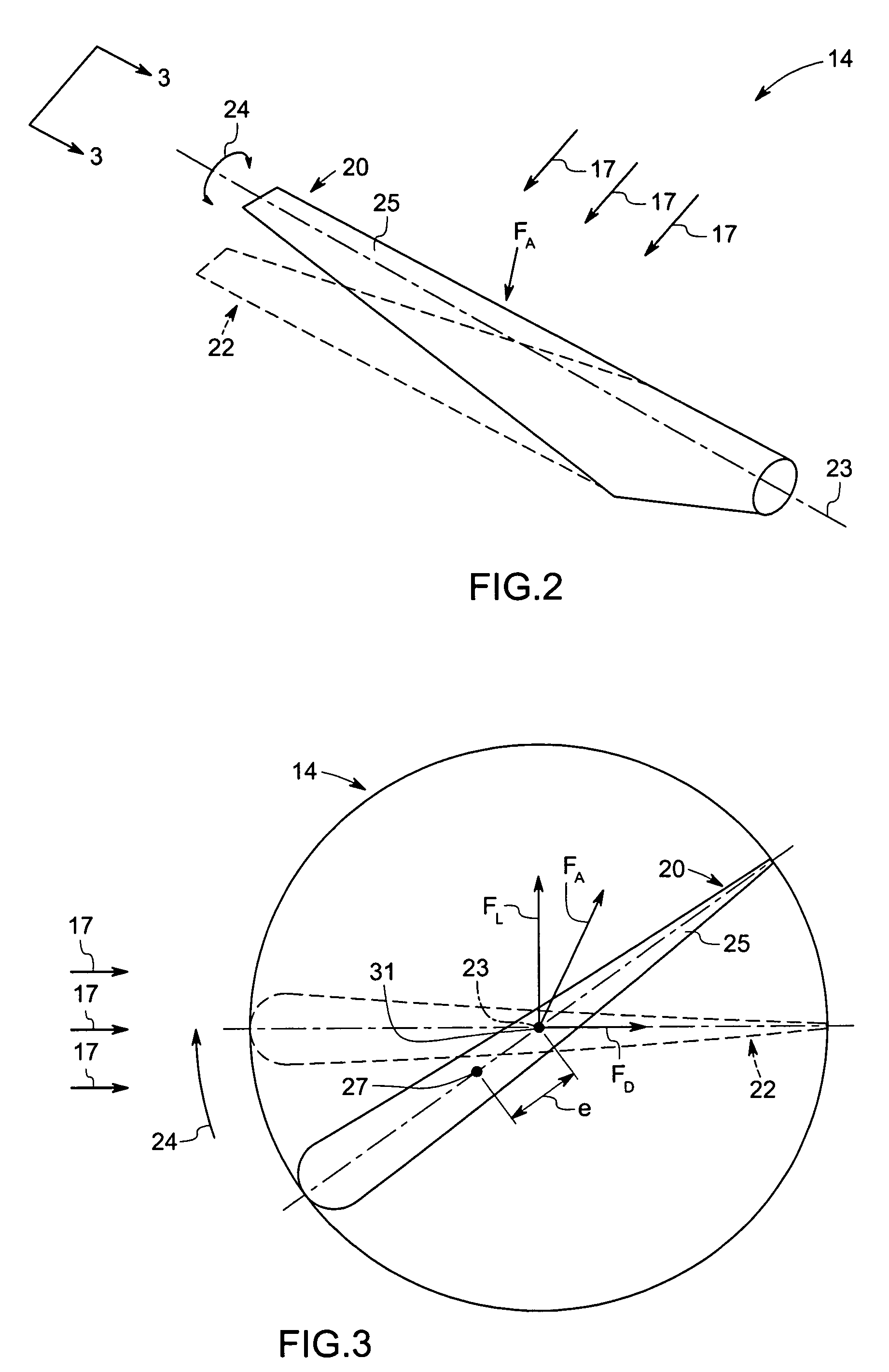
[0018]The technique described below provides a system and method for improving wind turbine performance by alleviating bending and shear loads on the wind turbine blades. The present technique employs the use of a passively adaptive wind turbine blade that modifies its aerodynamic configuration based on the extent of wind loading on the blade, thereby attenuating cyclic loading of the blade due to turbulence in wind velocity. As discussed in detail below, certain embodiments of the present technique employ a variety of internal support structures, such as C-shaped, Z-shaped, and unsymmetrical structures, which effectuate a twisting motion of the turbine blades in response to bending caused by strong turbulent / cyclic winds. This twisting motion causes the turbine blades to become more closely aligned with the direction of the wind, thereby reducing wind loads on the turbine blades. This reduced cyclic loading, in turn, extends fatigue life of the blade as well as other load bearing s...


PUM


Abstract

In accordance with certain embodiments, a wind turbine blade includes an outer skin and an internal support structure. The skin has a closed airfoil shape and includes an outer surface, an inner surface, and opposite sides along a length of the blade. The internal support structure is disposed within the closed airfoil shape. The internal support structure includes at least one shear load bearing member disposed across the opposite sides and oriented lengthwise along the length of the blade. The internal support structure further includes a plurality of bending load bearing members disposed along the inner surface in a lengthwise direction along the length of the blade. The internal support structure is configured to position a shear center and a center of aerodynamic pressure loading of the blade at different locations relative to one another.

Description

BACKGROUND[0001]The invention relates generally to wind turbines, and particularly to rotating blades of wind turbines. Specifically, embodiments of the present technique provide a system and method to passively attenuate wind loads on the rotating blades of wind turbines.[0002]Wind turbines are regarded as environmentally safe and relatively inexpensive alternative sources of energy that utilize wind energy to produce electricity. A wind turbine generally includes a rotor having multiple blades, which transform wind energy into a rotational motion of a drive shaft. The drive shaft is rotationally coupled to a rotor of a generator, which transforms the rotational energy into electrical power.[0003]Wind turbine blades often operate under atmospheric turbulence, resulting from disturbances in wind velocity. Such disturbances subject the wind turbine blades to aerodynamic bending and shear loads, which result in fatigue of the rotating blades. At times, these loads can be relatively hi...

Claims


Application Information

Patent Timeline
Patent Type & Authority Patents(United States)
IPC IPC(8): F03B15/06
CPCF03D1/0675Y02E10/721F05B2240/301F05B2240/30Y02E10/72
Inventor DELEONARDO, GUY WAYNEFINN, SCOTT ROGERFINNIGAN, PETER MICHAELKASPERSKI, DONALD JOSEPH
Owner LM WIND POWER US TECH APS
Learn More