Re-circulation and reuse of dummy-dispensed resist

a technology of resist and dummy, applied in the field of dummy-dispensed resist, can solve the problems of affecting coating thickness, easy to trap airborne particles, defects, etc., and achieve the effects of facilitating the dispensing of resist, promoting a relatively free-flow of resist, and reducing was

Inactive Publication Date: 2006-12-26
GLOBALFOUNDRIES INC
View PDF22 Cites 20 Cited by
  • Summary
  • Abstract
  • Description
  • Claims
  • Application Information

AI Technical Summary

Benefits of technology

[0015]The present invention relates to a system and methodology to facilitate dispensing a resist while promoting a relatively free-flow of the resist through a dispense head, yet mitigating waste associated with a dummy-dispensing process. This can be achieved by employing a dummy-dispensed resist through the dispense head to facilitate a substantially unimpeded application of the resist in the dispense head in support of a lithographic process, wherein dummy-dispensing of the resist can occur at times other than when the lithographic process occurs. Resist that is employed in the dummy-dispense process can then be captured in a reservoir and returned to the dispense head in a re-circulative manner in order to mitigate waste.

Problems solved by technology

Small changes, caused for example by the evaporation of solvent during spin-speed ramp-up, can significantly affect coating thickness.
Because the resist is sticky, it can easily entrap airborne particles.
Defects can also be caused by air bubbles entrapped in the resist.
A common cause of defects and variability in resist coatings is the tendency of resists to dry rapidly and form residues on the dispense head.
These residues can occlude the dispense head orifice, affecting the amount and pattern in which the resist is dispensed.
In addition, flakes of dried resist and particles that crystalize from the resist solution as it dries may contaminate the resist solution or fall directly onto the substrates.
This method can be effective, but resist solutions are expensive and the amount of wasted resist involved in dummy dispensing cause this method to be prohibitive.
One difficulty with this approach is that solvent in the dispense head may dilute subsequently dispensed resist solution.
Diluting the resist solution affects its viscosity and results in variable coating thickness.
The dispense head can be flushed with resist solution before dispensing on substrates, but as with dummy dispensing this involves the waste of expensive resist solution.
Unfortunately, it is difficult to maintain the correct solvent atmosphere, particularly in a location in which the dispense head can be easily placed and removed.
Additionally, the required apparatus is complicated and residues may still form.
However, some resist remains in the dispense head and the remaining resist tends to dry very quickly.
In view of the above, there remains an unsatisfied need for an apparatus and method of dispensing resist that is convenient, uncomplicated, does not waste expensive resist solution, and keeps the dispense head relatively free of residues and contaminates.

Method used


Image

  • Re-circulation and reuse of dummy-dispensed resist
  • Re-circulation and reuse of dummy-dispensed resist
  • Re-circulation and reuse of dummy-dispensed resist

Examples


Embodiment Construction

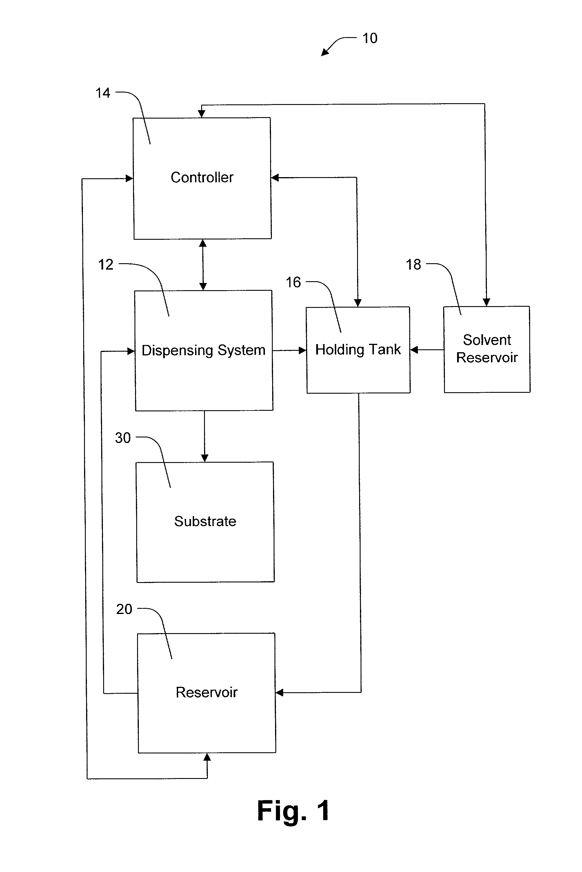
[0029]Referring initially to FIG. 1, a block diagram of a system 10 illustrates resist dispensing according an aspect of the present invention. The system 10 provides a closed loop system that reduces and mitigates drying of resist in a dispense head, for example. The system 10 maintains dispensing of resist at a slow rate, even between resist depositing steps, to reduce drying and yet, mitigates waste of resist by capturing at least some dispensed resist. The system 10 includes a controller 14, dispensing system 12, substrate 30, reservoir 20, holding tank 16 and a solvent reservoir 18.

[0030]The controller 14 is operatively coupled to the dispensing system 12, the holding tank 16, the solvent reservoir 18 and the reservoir 20. The controller 14 is adapted to control the operation of the dispensing system 12, the holding tank 16, the solvent reservoir 18 and the reservoir 20, wherein the controller 14 includes at least one processor (not shown) and a memory (not shown) to direct the...


PUM


Abstract

The present invention provides a system and methodology for dummy-dispensing resist though a dispense head while mitigating waste associated with the dummy-dispense process. The dummy dispensed resist is returned to a reservoir from which it was taken. Between substrate applications, the dispense head can be positioned to dispense resist into a return line. The flow of resist from the dispense head keeps resist from drying at the dispense head. By funneling the dummy-dispensed resist into a return line with low volume, for example, waste from the dummy-dispensing process can be mitigated.

Description

REFERENCE TO RELATED APPLICATION[0001]This application claims the benefit of U.S. Provisional Patent Application Ser. No. 60 / 242,638, which was filed Oct. 23, 2000, entitled RE-CIRCULATION AND REUSE OF DUMMY-DISPENSED RESIST.TECHNICAL FIELD[0002]The present invention generally relates to semiconductor processing, and in particular to an apparatus for dispensing resist.BACKGROUND OF THE INVENTION[0003]In the semiconductor industry, there is a continuing trend toward higher device densities. To achieve these higher densities, there have been, and continue to be, efforts toward scaling down the device dimensions (e.g., at submicron levels) on semiconductor wafers. In order to accomplish such high device packing density, smaller and smaller features sizes are required. This may include the width and spacing of interconnecting lines, spacing and diameter of contact holes, and the surface geometry such as corners and edges of various features.[0004]The requirement of small features with c...

Claims


Application Information

Patent Timeline
Patent Type & Authority Patents(United States)
IPC IPC(8): B05B1/28B05B15/04B05B3/00
CPCB05B15/02H01L21/6715B05C11/08B05B15/50
Inventor RANGARAJAN, BHARATHSUBRAMANIAN, RAMKUMARPHAN, KHOI A.QUINTO, URSULA Q.TEMPLETON, MICHAEL K.
Owner GLOBALFOUNDRIES INC
Why Eureka
Try Eureka