
Printing apparatus and printing method

Inactive Publication Date: 2006-12-26
CASIO COMPUTER CO LTD
View PDF66 Cites 40 Cited by
  • Summary
  • Abstract
  • Description
  • Claims
  • Application Information

AI Technical Summary

Benefits of technology

[0015]It is an object of the present invention to provide an apparatus and a method for printing which realize high resolution digital image printing within a short time while reducing costs.

Problems solved by technology

Since filmed photo must be developed at a photo processing shop, it takes a long time to develop photos.
Therefore, it is difficult to realize high quality and high speed printing in home.
A photo processing shop which can handle digital images can print the images with high quality, however, it also takes a long time to image developing as well as the case of film photo developing.
Regardless of filmed image or digital image, image processing for printing costs a user.
For example, a photo processing shop requires fees for developing and printing services, and a personal printer costs for expendable supplies such as paper and inks.
If several sets of the print data are supplied to the printing apparatus 190, it takes a long time to process them, therefore, it is difficult to realize high speed printing even if the apparatus is equipped with a plurality of printing mechanisms.

Method used


Image

  • Printing apparatus and printing method
  • Printing apparatus and printing method
  • Printing apparatus and printing method

Examples


first embodiment

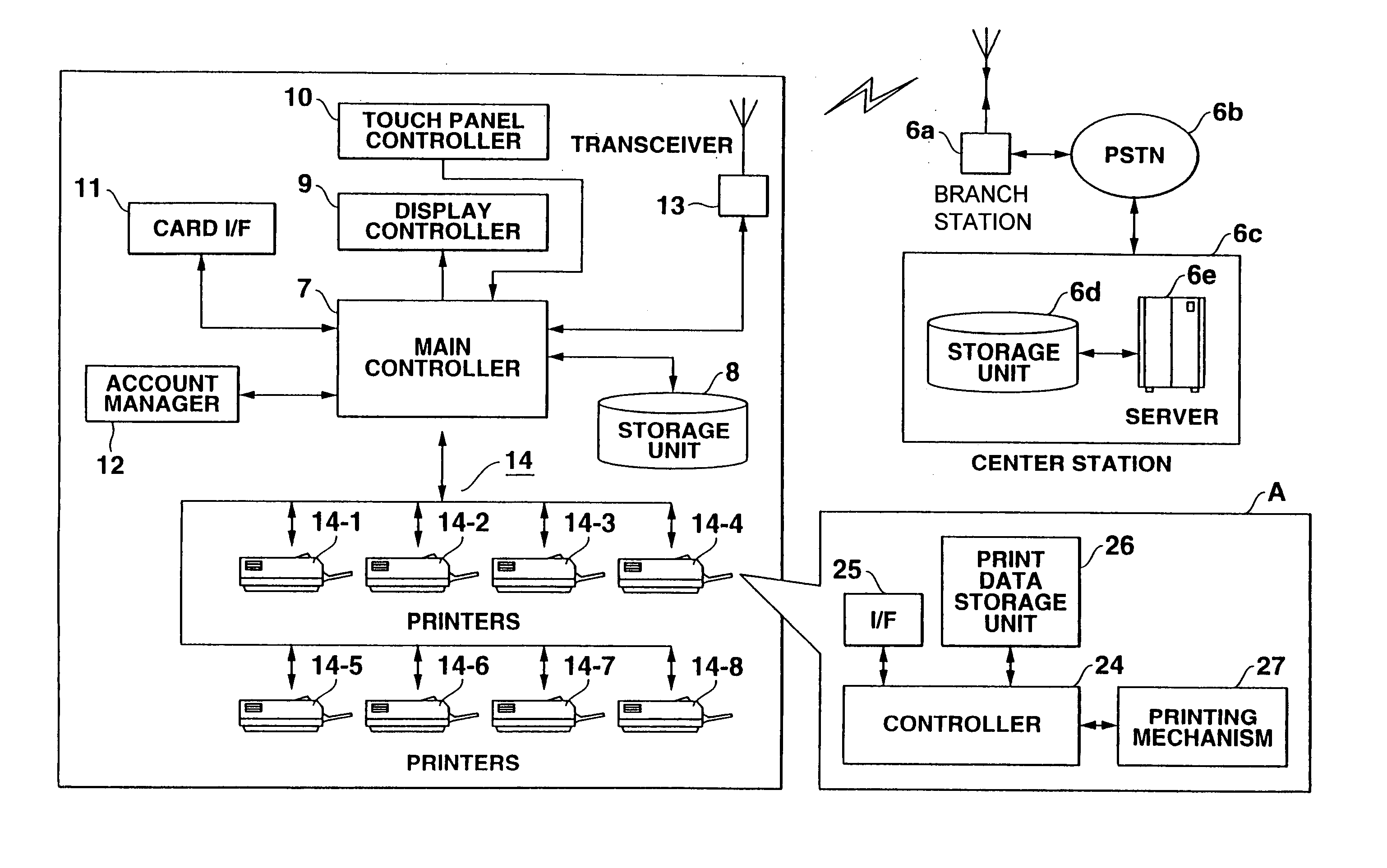
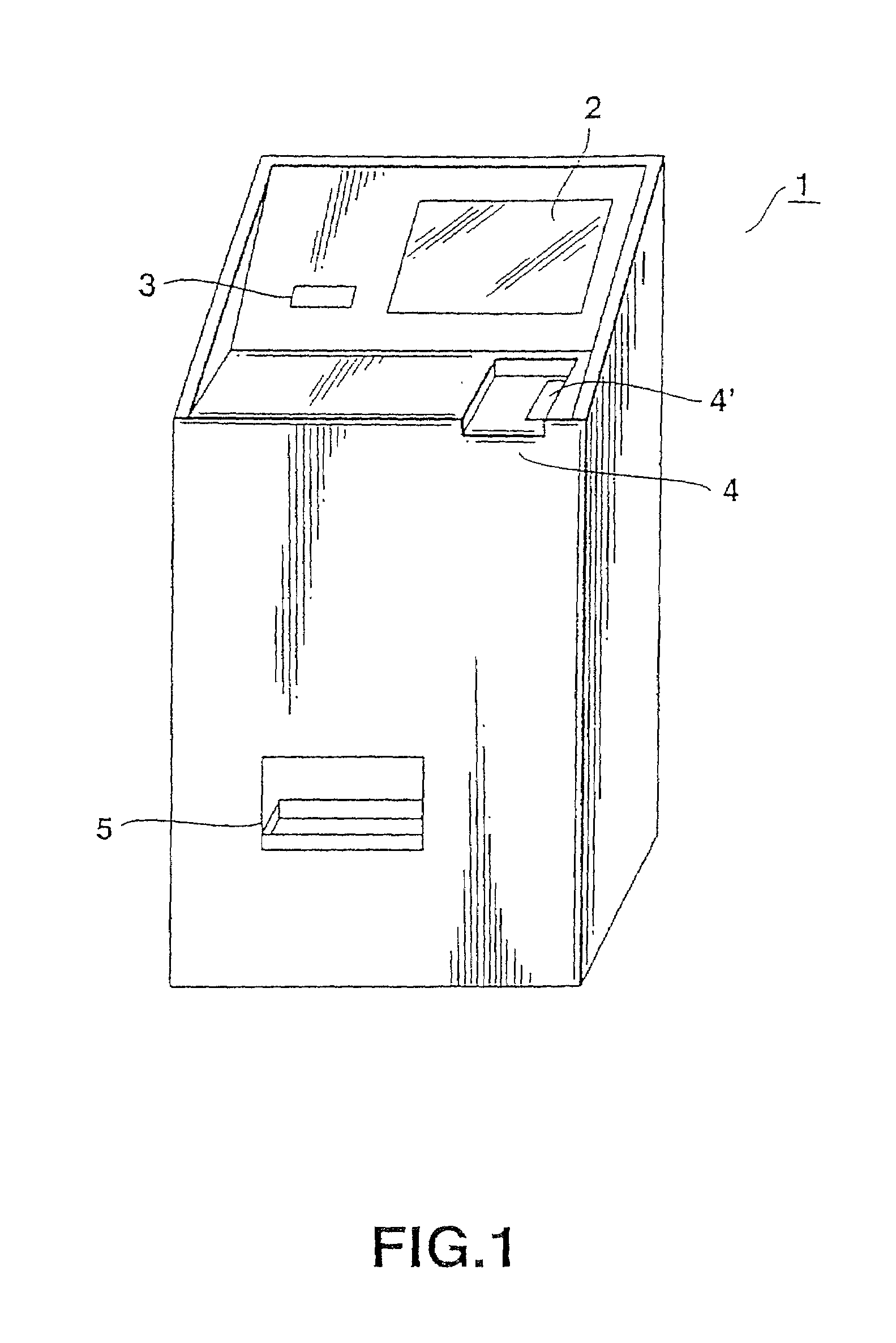
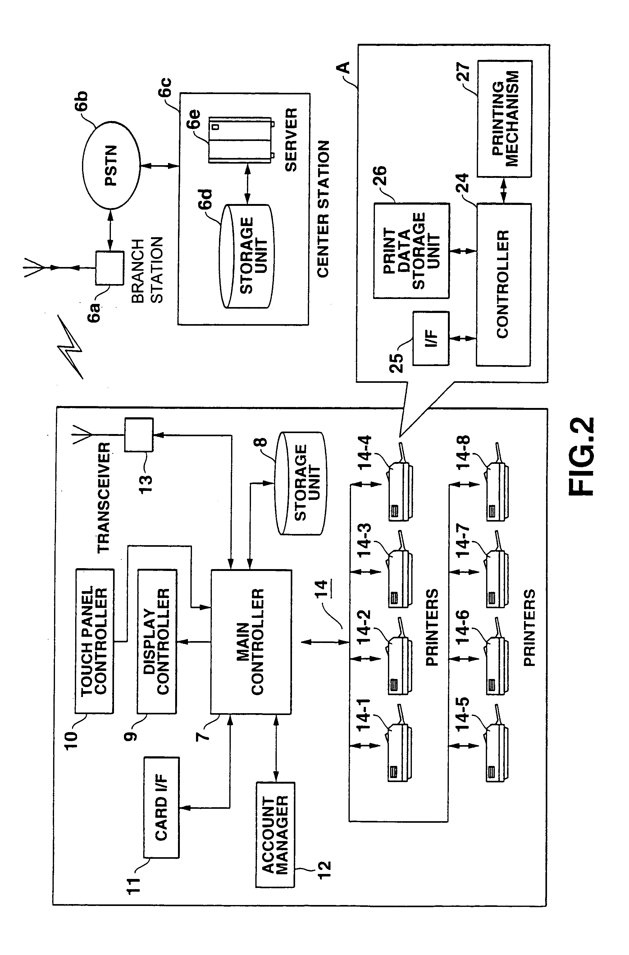
[0148]FIG. 1 is a diagram showing a print vending machine 1 according to this embodiment. The print vending machine 1 is designed to be placed, for example, on the streets or in buildings such as office buildings. As shown in FIG. 1, the print vending machine 1 comprises a display / operation panel 2, a media slot 3, a payment / return slot 4, and a sheet outlet 5.

[0149]The display / operation panel 2 comprises a display such as a liquid crystal display, and a touch panel (tablet) formed on the display. The display displays keys, buttons, icons, and the like, and a user touches them. The display / operation panel 2 senses where the user touches, and input a signal representing the touch position.

[0150]The display / operation panel 2 also displays thumbnail images, and mode select icons which provide the user with options free service or pay service. The user selects the service mode and inputs print quantity through the display / operation panel 2.

[0151]The media slot 3 accepts a recording medi...

second embodiment

[0237]FIG. 14 is a diagram showing exterior structure of an automatic print vending machine according to this embodiment. The print vending machine 101 comprises a display / operation panel (display and touch panel) 102, input keys 103, media slots 104a to 104e, indicator lamps 105a to 105e, a fee display 106, a bill slot 107a, a coins slot 107b, a cancel button 108, a receipt insert slot 109, a receipt outlet slot 110, a change / return outlet 111, and a print outlet 112, which are arranged on a front surface of the vending machine 101. Further, sub displays 113 are formed on both sides of the vending machine 101.

[0238]The display / operation panels (display and touch panel) 102 comprises a display such as a liquid crystal display, and an operation panel which operable by a user through keys, buttons, icons, and the like on the display which are, for example, indexed by the user's finger.

[0239]The display / operation panel (display and touch panel) 102 displays, for example, thumbnailed im...


PUM


Abstract

A photographic print vending apparatus is provided which comprises a media accepting unit which accepts a recording medium having photographic image information stored thereon. An image information reader reads the image information from the recording medium, and a plurality of printers print images based on image data from a processor connected to the image information reader and an advertisement information storage unit. When an advertisement printing mode is set, the processor reads the advertisement information from the advertisement information storage unit, synthesizes the read advertisement information and the image information read by the image information reader, and supplies the synthesized information to the printers as image data.

Description

CROSS REFERENCE TO RELATED APPLICATION[0001]This application is a U.S. National Phase Application under 35 USC 371 of International Application PCT / JP00 / 04281 (published in English) filed Jun. 29, 2000.TECHNICAL FIELD[0002]The present invention relates an apparatus and method for printing digital images, more particularly to an apparatus and method for printing a digital image with synthesizing an advertisement image.[0003]The present invention also relates to a printing apparatus having a plurality of printers each comprising an image forming unit and a printing mechanism, and a method of printing with using the printing apparatus.BACKGROUND ART[0004]To develop filmed photo, a user usually brings a film to a photo processing shop.[0005]Digital devices such as a digital camera and a scanner have been spread to personal use. Images captured or scanned by such the digital device are printed by, for example, a printer connected to a personal computer. Since digital images can be record...

Claims


Application Information

Patent Timeline
IPC IPC(8): G06F15/00G06Q30/00H04N1/00
CPCG06Q30/02H04N1/00132H04N1/00143H04N1/00161H04N1/00175H04N1/00188H04N1/00339H04N1/00411G06K15/02
Inventor NIMURA, WATARUMIZUSHINA, TAKAHIROTAKAHASHI, HIROKIKASAHARA, TAKESHIMIZUNO, KIMIYASU
Owner CASIO COMPUTER CO LTD
Learn More