
Apparatus for switching data in high-speed networks and method of operation

a high-speed network and data switch technology, applied in data switching networks, store-and-forward switching systems, digital transmission, etc., can solve the problems of slow inability to achieve breakthroughs in bottlenecks, and inability to build scalable switches in the future. , to achieve the effect of fast internal speed-up of n output buffers

Active Publication Date: 2006-12-26
STMICROELECTRONICS LTD
View PDF10 Cites 39 Cited by
  • Summary
  • Abstract
  • Description
  • Claims
  • Application Information

AI Technical Summary

Benefits of technology

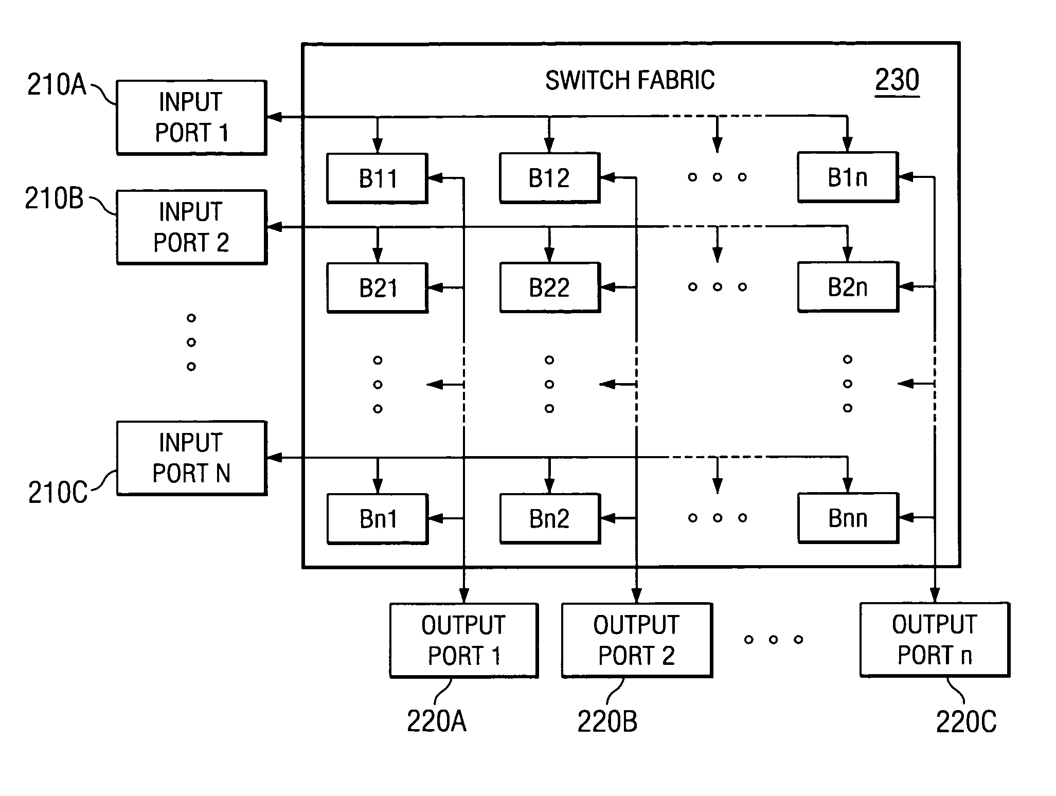
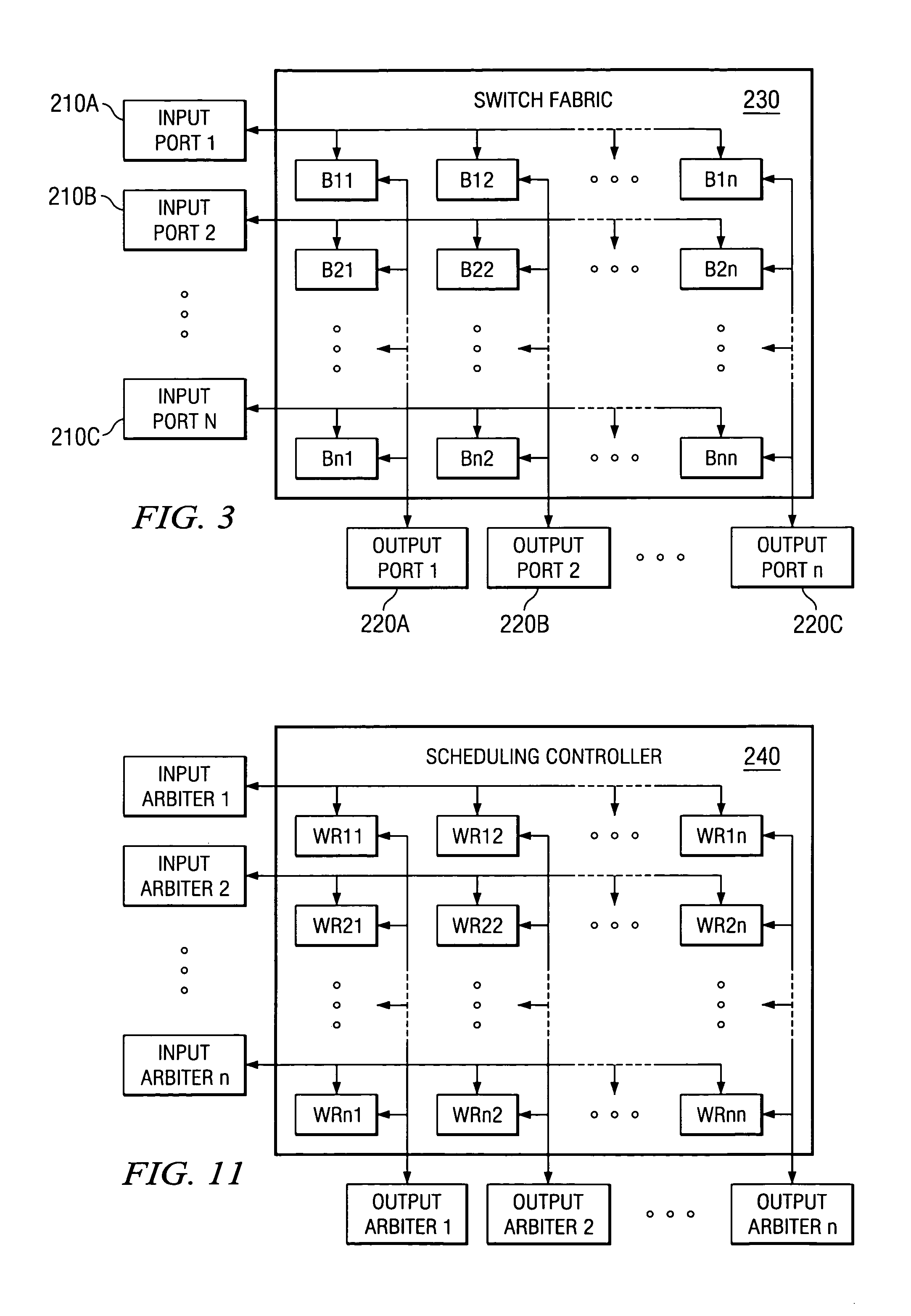
[0022]Unlike previous work that tried to lower the algorithmic complexity of scheduling a VOQ switch for good performances, the present invention solves the scheduling problem of a VOQ switch by a hybrid algorithmic and architectural method. In brief, a new buffering block is introduced into the original VOQ / CIOQ switch and distributive scheduling algorithms with far lower complexities are elaborated to achieve good switch performances.
[0030]According to yet another embodiment of the present invention, the N×N internal buffers are configured within the N output ports such that each output port has a fast internal speed-up of N output buffer that is shared at least partially by cells from all input ports.

Problems solved by technology

Unfortunately, both approaches are reaching their limits without achieving breakthroughs of the bottlenecks.
Consequently, it is anticipated that little can be done in the future to build scalable switches along these two exiting directions to meet the ever-increasing network bandwidth.

Method used


Image

  • Apparatus for switching data in high-speed networks and method of operation
  • Apparatus for switching data in high-speed networks and method of operation
  • Apparatus for switching data in high-speed networks and method of operation

Examples


Embodiment Construction

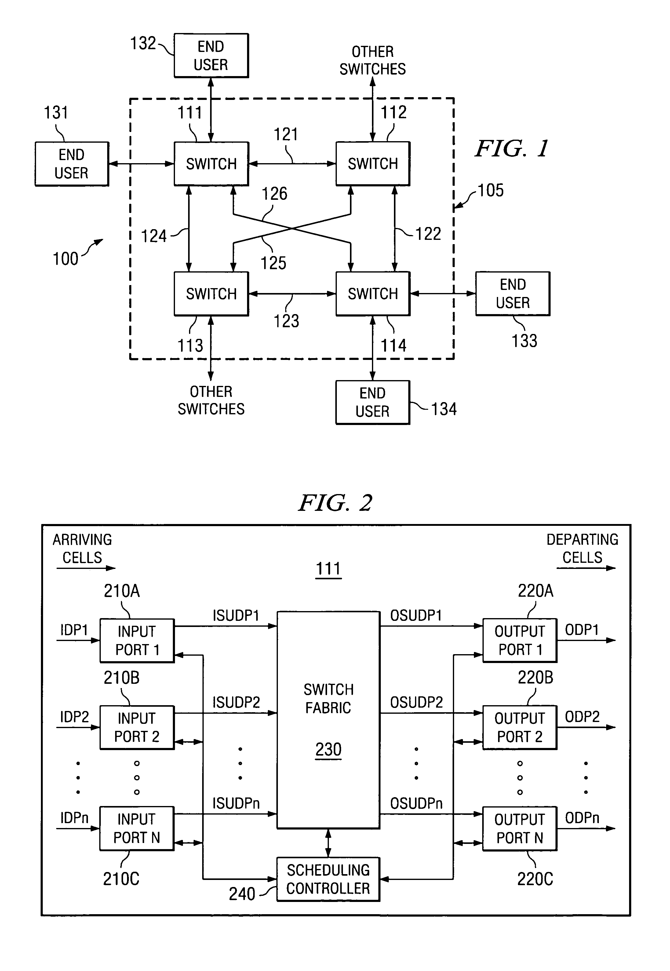
[0046]FIGS. 1 through 11, discussed below, and the various embodiments used to describe the principles of the present invention in this patent document are by way of illustration only and should not be construed in any way so as to limit the scope of the invention. Those skilled in the art will understand that the principles of the present invention may be implemented in any suitably arranged fixed size packet data switch.

[0047]FIG. 1 illustrates an exemplary packet switching network 100 containing packet switches 111–114 in accordance with the principles of the present invention. Packet switching network 100 contains a subnetwork 105, indicated by a dotted line, comprising packet switches 111–114, that interconnects end-user devices 131–134 with each other and with other switches (not shown) and other end-user devices (not shown) associated with packet switching network 100. Packet switches 111–114 are interconnected by data links 121–126. Subnetwork 105 is intended to be a represe...


PUM


Abstract

A packet switch for switching cells comprising fixed-size data packets. The packet switch comprises: 1) N input ports for receiving and storing cells in input queues; 2) N output ports for receiving and storing cells from the N input ports in output queues; 3) a switch fabric for transferring the cells from the N input ports to the N output ports, the switch fabric comprising an internally buffered crossbar having N×N internal buffers, wherein each internal buffer is associated with a crosspoint of one of the N input ports and one of the N output ports; and 4) a scheduling controller for selecting a first one of a plurality of queued head-of-line (HOL) cells from the input queues to be transmitted to a first one of the N×N internal buffers according to a fair queuing algorithm in which each of the queued HOL cells is allocated a weight of Rij and wherein the scheduling controller selects a first one of a plurality of HOL cells buffered in a second one of the N×N internal buffers to be transmitted to a first one of the output queues according to a fair queuing algorithm in which each of the internally buffered HOL cells is allocated a weight of Rij.

Description

CROSS-REFERENCE TO RELATED APPLICATIONS[0001]The present invention is related to those disclosed in U.S. patent application Ser. No. 10 / 036,809, filed concurrently herewith, entitled “SCALABLE TWO-STAGE VIRTUAL OUTPUT QUEUING SWITCH AND METHOD OF OPERATION”. Application Ser. No. 10 / 036,809 is commonly assigned to the assignee of the present invention. The disclosure of the related patent application is hereby incorporated by reference for all purposes as if fully set forth herein.TECHNICAL FIELD OF THE INVENTION[0002]The present invention is generally directed to packet switching networks and, more specifically, to a high-throughput scheduler and related scheduling algorithms for use in a fixed-size data packet switch.BACKGROUND OF THE INVENTION[0003]Packet switching involves the transmission of data in packets through a data network. Fixed-sized packets are referred to as cells. Each block of end-user data that is to be transmitted is divided into cells. A unique identifier, a sequ...

Claims


Application Information

Patent Timeline
Patent Type & Authority Patents(United States)
IPC IPC(8): H04L12/56H04L12/54H04L12/70H04L12/933
CPCH04L12/5601H04L49/106H04L2012/5679H04L2012/5681H04L2012/5683
Inventor NONG, GE
Owner STMICROELECTRONICS LTD
Learn More