Synthetic resin pipe

a synthetic resin and pipe technology, applied in the direction of flexible pipes, pipes, mechanical equipment, etc., can solve the problems of increasing the weight reducing the flexibility unable to achieve the goal of forming a flat outer surface of synthetic resin pipes, etc., to achieve the effect of improving water-stop performance, sacrificing flexibility, and reducing the weigh

Inactive Publication Date: 2007-01-02
KANA FURETSUKUSU KOOHOREESHON
View PDF13 Cites 33 Cited by
  • Summary
  • Abstract
  • Description
  • Claims
  • Application Information

AI Technical Summary

Benefits of technology

[0009]The outer pipe may be formed thicker to prevent the deformation of the outer pipe, however, it may increase the weight of the synthetic resin pipe and decrease the flexibility of the synthetic resin pipe.
[0024]According to the synthetic resin pipe of the present invention, it is possible to improve the water-stop performance because the outer pipe is retained flat, and in addition, the pipes may be connected to each other without troublesome connecting work. It is further possible to improve, without sacrificing the flexibility, the pressure-proof flatness strength resisting against the external pressure applied to the synthetic resin pipe.

Problems solved by technology

However, the above conventional synthetic resin pipe cannot prevent a deformation of the portion connecting the convex portion in outer pipe into a curved shape resulting from its shrinkage in the pipe axis direction caused when the synthetic resin pipe is hardened.
When the curving degree becomes large, an object to form a flat outer surface in synthetic resin pipe cannot be achieved.
The outer pipe may be formed thicker to prevent the deformation of the outer pipe, however, it may increase the weight of the synthetic resin pipe and decrease the flexibility of the synthetic resin pipe.

Method used


Image

  • Synthetic resin pipe
  • Synthetic resin pipe
  • Synthetic resin pipe

Examples


Embodiment Construction

[0044]The present invention will be described in detail based on the following embodiments with reference to the drawings.

a. Synthetic Resin Pipe Having Outer Pipe with Shape Retaining Material for Outer Pipe in Whole Body of Pipe.

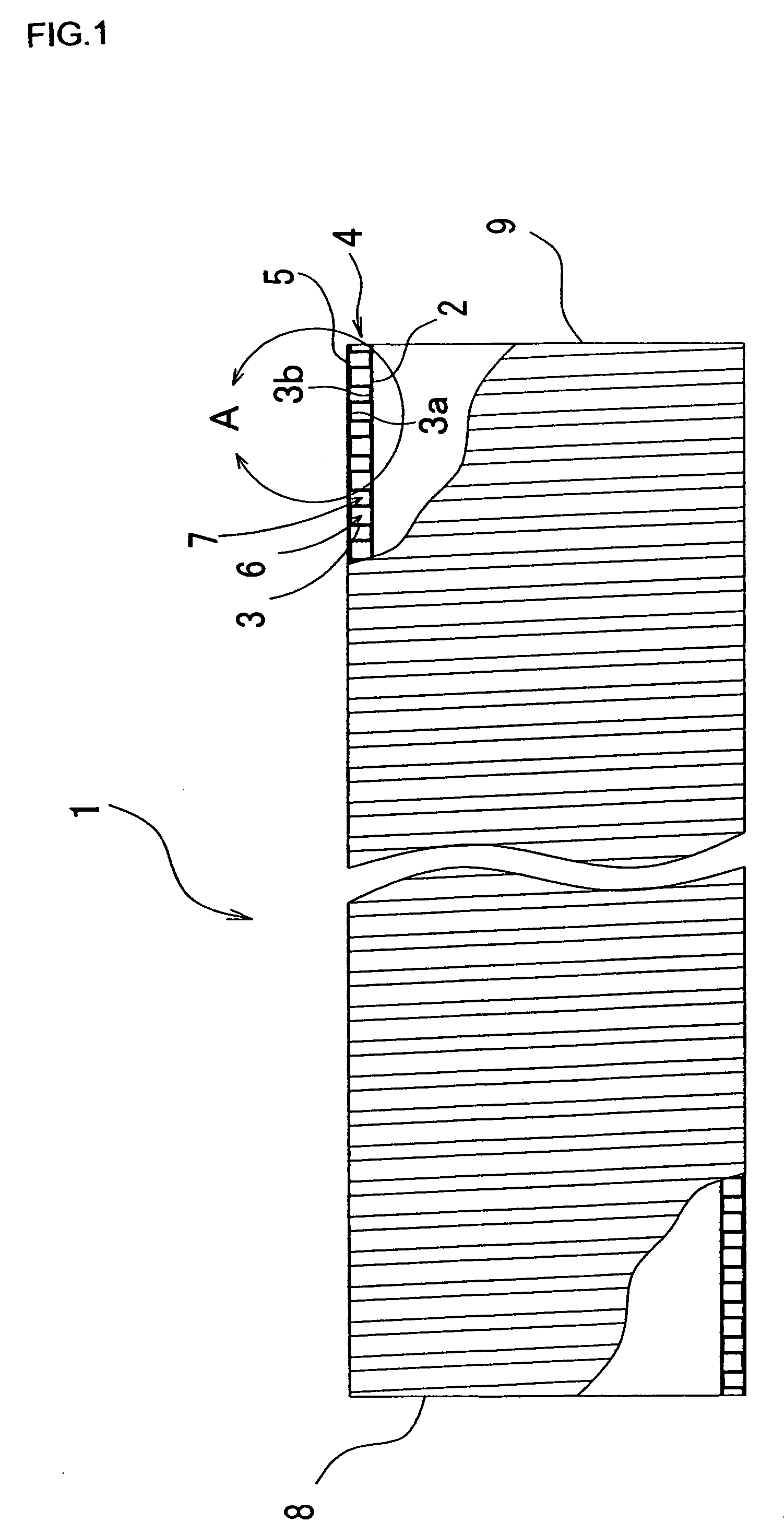
[0045]FIG. 1 is a view of an entire structure of a synthetic resin pipe according to the present invention, and illustrates a partially broken cross sectional view.

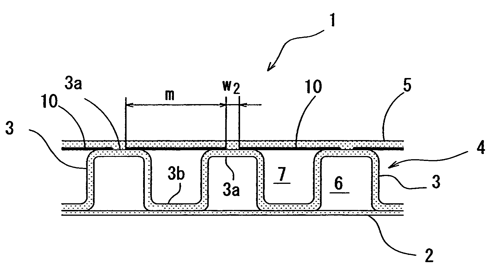
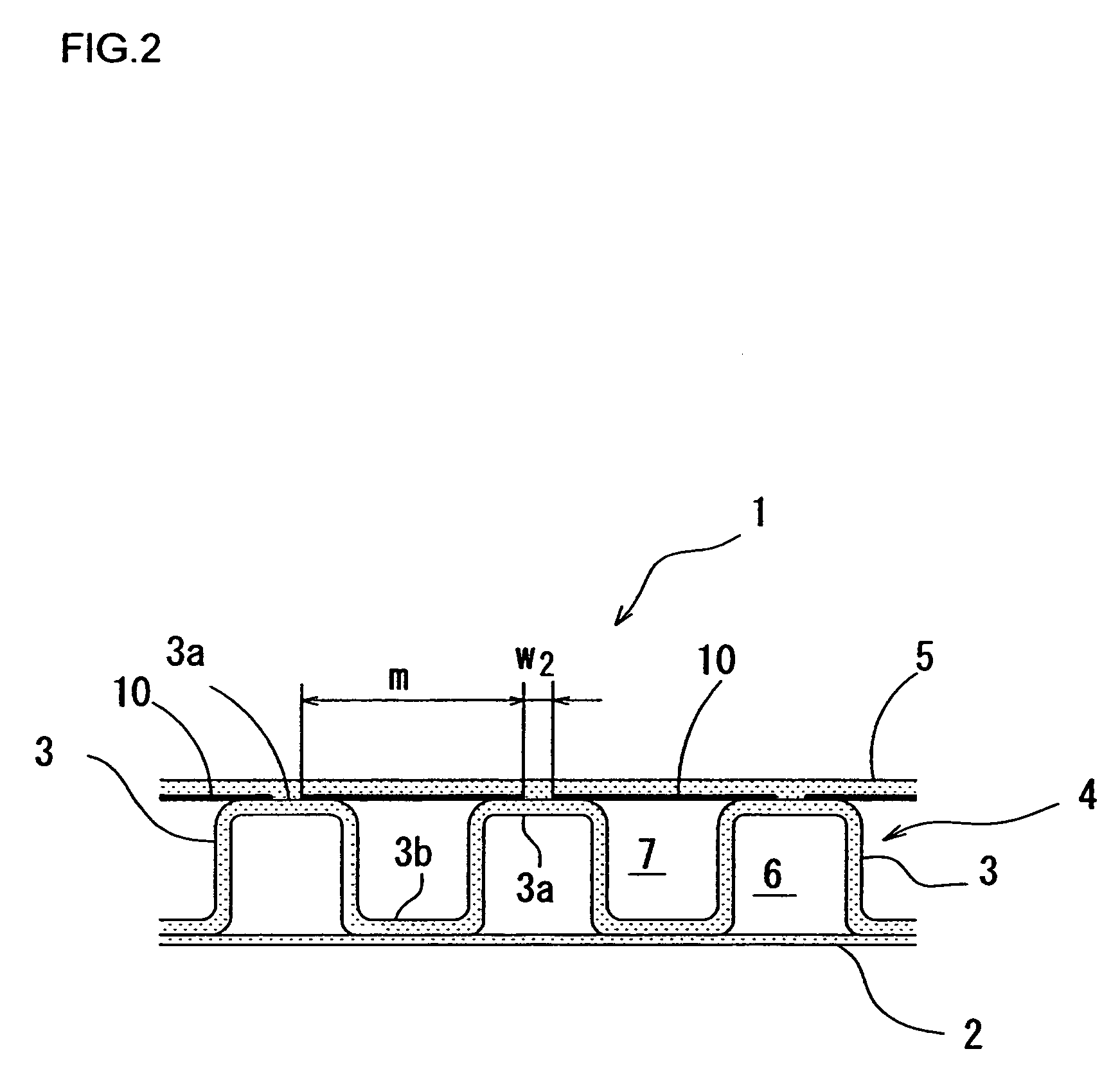
[0046]A synthetic resin pipe 1 includes an inner pipe 2 having a flat and smooth inner surface by rolling a belt-like synthetic resin. A spiral reinforcing part 4 is formed by forming a projected rim 3 in a spiral at a predetermined pitch in an outer body wall of the inner pipe 2. As a result, convex portions 3a and concave portions 3b are alternately formed along the pipe axis direction, on the outer surface of the inner pipe 2.

[0047]An outer pipe 5 is formed so as to bridge the convex portions 3a of the projected rim 3.

[0048]In the drawing, a reference numeral 6 represents a space enclosed by ...


PUM


Abstract

An object of the present invention is to provide a synthetic resin pipe configured to perform water stop accurately by forming a part connecting convex portions of an outer pipe to be flat without reducing flexibility in order to compose a synthetic resin pipe having flat inner and outer surfaces. A synthetic resin pipe according to the present invention includes an inner pipe formed by spirally winding a belt-like synthetic resin; a spiral reinforcing part formed by spirally winding a synthetic resin having a projected rim with convex portions projecting outside; an outer pipe of belt-like synthetic resin provided so as to connect a part or all of the convex portions arranged in a pipe axis direction; and a shape retaining material for the outer pipe made of a belt-like metal sheet for retaining a shape of the outer pipe flat and buried in or provide to an inner surface of the outer pipe; wherein the shape retaining material for the outer pipe is a synthetic resin pipe wound around the convex portions of the projected rim at predetermined intervals and connecting the convex portions of the projected rim.

Description

BACKGROUND OF THE INVENTION[0001]1. Field of the Invention[0002]The present invention relates to a synthetic resin pipe which is mainly used in the underground. More particularly, the present invention relates to a synthetic resin pipe, in which an inner surface and an outer surface are flat and smooth, used for leading communication cables or power transmission wires, or used as a water pipe for water and sewerage.[0003]2. Description of the Related Art[0004]Synthetic resin corrugated pipes are conventionally used. In a synthetic resin corrugated pipe, an inner surface is formed flat and smooth and an outer surface includes projecting parts and depression parts alternately in the pipe axis direction to withstand strong pressures from inside or outside.[0005]This type of corrugated pipe has concave portions and convex portions on the outer surface and a resistance for pulling the pipe in is large so that a smooth working process may not be obtained. Further, in order to connect this...

Claims


Application Information

Patent Timeline
Patent Type & Authority Patents(United States)
IPC IPC(8): F16L11/00
CPCF16L11/112
Inventor KANAO, SHIGEKI
Owner KANA FURETSUKUSU KOOHOREESHON
Why Eureka
Try Eureka