
Device and method to control and/or regulate a pressure level

Inactive Publication Date: 2007-01-02
ROBERT BOSCH GMBH
View PDF25 Cites 14 Cited by
  • Summary
  • Abstract
  • Description
  • Claims
  • Application Information

AI Technical Summary

Benefits of technology

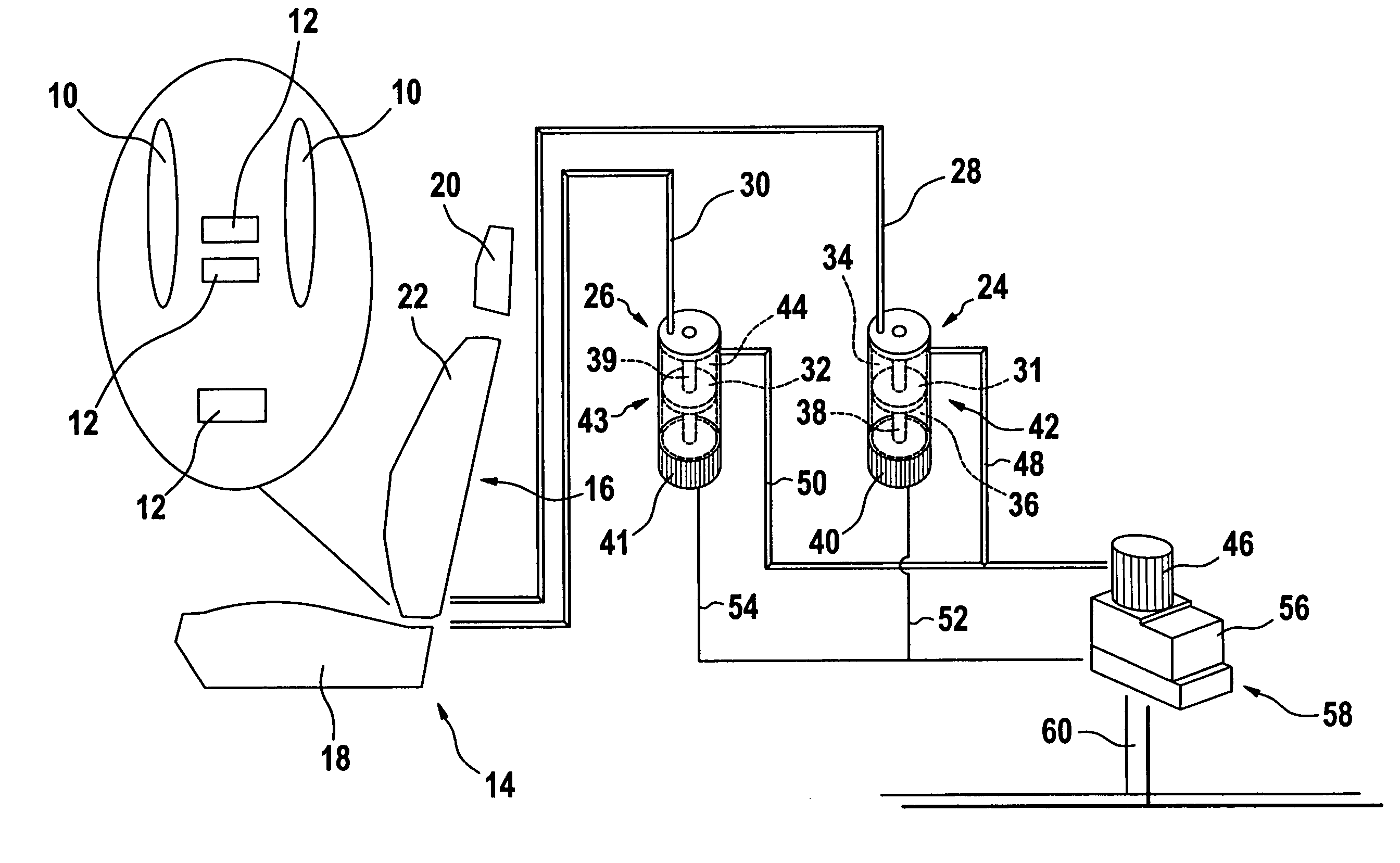
[0008]The device in accordance with the invention or the method in accordance with the invention has the advantage as compared with state of the art systems that control and / or regulation of the pressure level is possible without losses of the working fluid. In the case of state of the art systems, a pump fills a volume that is used as a working reservoir. The seating system is pneumatically liked to this volume in such a way that a filling of the air cushions of the seat takes place via the volume of a working fluid located in the intermediate reservoir. In this process, pressure sensors monitor the pressure of the air cushions. When the seat's air cushions are deaerated, the air is deflated, i.e., released to the atmosphere. For this reason, air always has to be re-fed to the system. This requires, among other things, a powerful and therefore both large as well as costly pump for the working fluid.
[0009]In the case of the system in accordance with the invention, no losses whatsoever of the working fluid occur in dynamic operation in an advantageous manner. Because of the means in accordance with the invention, it is possible to vary the volume connected with the recipients and thereby, since this is a closed system, automatically control the pressure in the recipients.
[0010]Because no losses of the working fluid occur in the proposed system, the system's pump can be restricted substantially in terms of its size. In addition, it is possible to dispense with a pressure accumulator in an advantageous manner so that the installation volume of the device in accordance with the invention is reduced considerably. Therefore, a completely self-sufficient system with a high savings in costs is the result. Such a system can be installed directly in a vehicle seat in an advantageous manner for example.

Problems solved by technology

This requires, among other things, a powerful and therefore both large as well as costly pump for the working fluid.
Therefore, a completely self-sufficient system with a high savings in costs is the result.

Method used


Image

  • Device and method to control and/or regulate a pressure level
  • Device and method to control and/or regulate a pressure level

Examples


Embodiment Construction

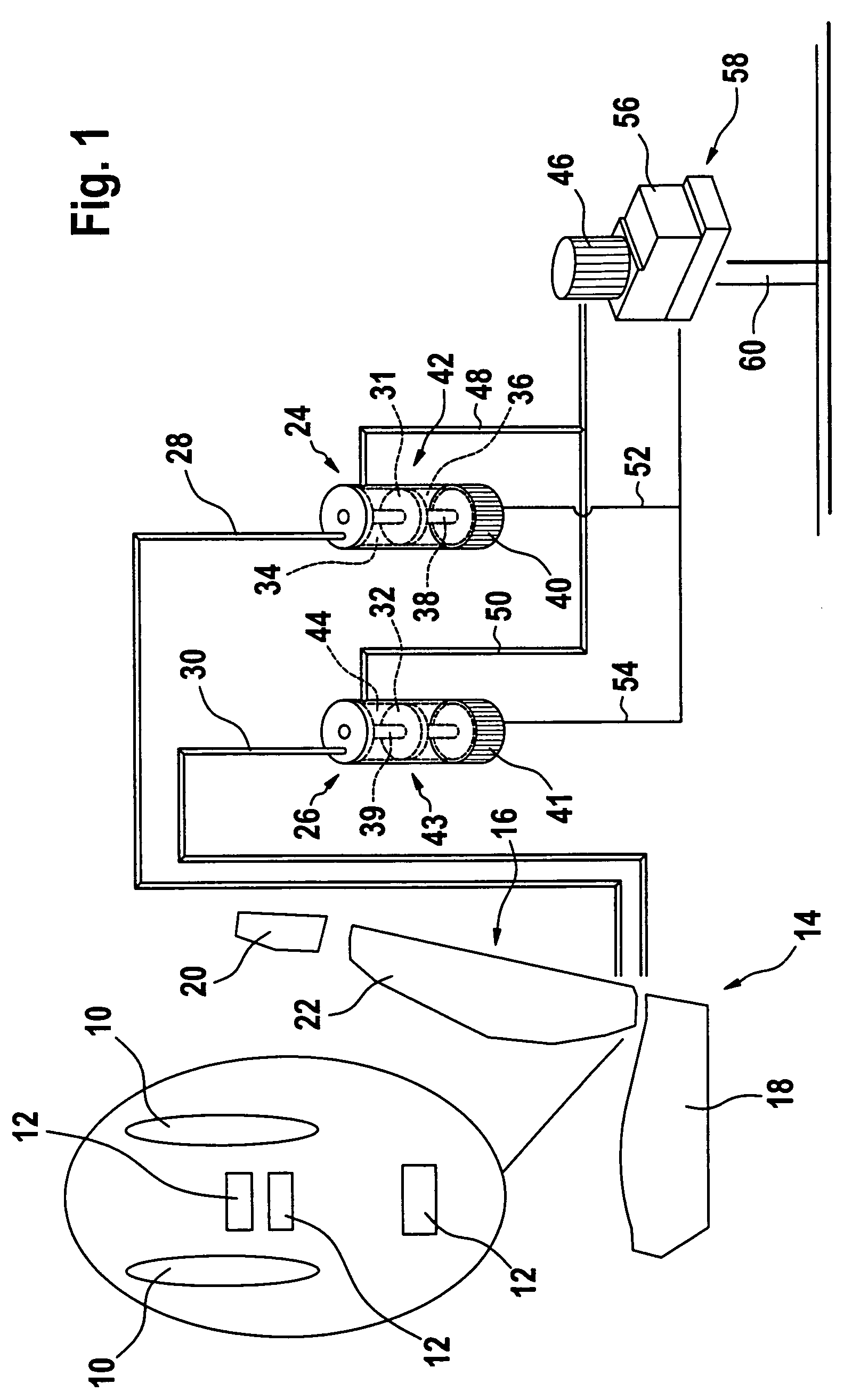
[0025]The only FIGURE in the description shows an exemplary embodiment of the device in accordance with the invention to control and / or regulate the pressure level of at least one volume variable recipient. In the case of the exemplary embodiment depicted, a plurality of recipients in the form of inflatable air cushions 10 or 12 are integrated into a seat 14, which is a motor vehicle seat in the exemplary embodiment depicted. To simplify the depiction, the recipients are shown next to the actual seat and divided into only two groups 10 or 12, whose pressure level can be controlled or regulated separately from each another. Of course, in the case of the real system, the recipients or the air chambers are integrated into the seat. Exemplary embodiments of the device in accordance with the invention other than the one that is depicted can naturally include a different number of recipients as well as a different number of control devices without straying from the spirit of the invention...


PUM


Abstract

A device to control and / or regulate the pressure level of at least one volume variable recipient (10, 12) of a pneumatic system, in particular a pneumatic system for a motor vehicle seat (14). Means (24, 26) make it possible to increase or reduce the pressure in the recipient (10, 12) in a reversible manner. In addition, a method to control and / or regulate the pressure level of at least one volume variable recipient (10, 12) of a pneumatic system, in particular a pneumatic system for a motor vehicle seat (14). The method varies the pressure level in the recipient (10, 12) by volume changes in a volume-adjusting element (24, 26) allocated to the recipient.

Description

BACKGROUND OF THE INVENTION[0001]The invention starts with a device to control and / or regulate the pressure level of at least one volume variable recipient of a pneumatic system, in particular a pneumatic system for a seat of a motor vehicle. In addition, the invention relates to a method to control and / or regulate the pressure level of such a system.[0002]Pneumatic control and / or regulating circuits are used in a variety of technical applications. Thus, these types of systems are used in the area of motor vehicle technology in order to increase the seating comfort of vehicle passengers, for example. In this connection, volume variable recipients, such as air cushions or bladders that are made preferably of synthetic material are embedded in the vehicle seat, and these recipients can be acted upon by a working fluid via a corresponding device in order to thereby adapt the vehicle seat to individual desires with regard to hardness and shape.[0003]A pneumatically controlled seat for a...

Claims


Application Information

Patent Timeline
IPC IPC(8): A47C4/54A47C7/14B60N2/90A47C7/46A47C27/08A47C27/10B60N2/00B60N2/02B60N2/52
CPCA47C7/467A47C27/082A47C27/083A47C27/10B60N2/002B60N2/4415B60N2/501B60N2/502B60N2/505B60N2/525B60N2/0244Y10S297/06B60N2/914
Inventor KIMMIG, DANIEL
Owner ROBERT BOSCH GMBH
Learn More