Stator for reciprocating motor and manufacturing method thereof

a technology of reciprocating motors and manufacturing methods, which is applied in the direction of positive displacement liquid engines, piston pumps, magnetic circuit shapes/forms/construction, etc., can solve the problems of increasing assembly time and complex assembly process, so as to reduce assembly time, improve productivity, and simplify assembly processes

Inactive Publication Date: 2007-01-02
LG ELECTRONICS INC
View PDF24 Cites 6 Cited by
  • Summary
  • Abstract
  • Description
  • Claims
  • Application Information

AI Technical Summary

Benefits of technology

[0011]Therefore, an object of the present invention is to provide a stator for a reciprocating motor and a manufacturing method thereof which are able to simplify assembling processes and to reduce assembling time, and thereby to improve productivity by bending an inner stator to be a cylindrical shape after laminating in straight shape.

Problems solved by technology

Therefore, the assembling time is increased and assembling process becomes complex.

Method used


Image

  • Stator for reciprocating motor and manufacturing method thereof
  • Stator for reciprocating motor and manufacturing method thereof
  • Stator for reciprocating motor and manufacturing method thereof

Examples


Embodiment Construction

[0034]Reference will now be made in detail to the preferred embodiments of the present invention, examples of which are illustrated in the accompanying drawings.

[0035]There may be a plurality of embodiments of a reciprocating motor according to the present invention. The preferred embodiments will be described as follows.

[0036]FIG. 4 is a cross-sectional view showing a reciprocating motor according to the present invention.

[0037]The reciprocating motor according to the present invention comprises: a stator assembly 2 supported by a frame (not shown) for forming a flux when an electric source is applied; and a magnet assembly 4 disposed with a predetermined air gap from the stator assembly 2 and reciprocated by an interaction with a flux generated from the stator assembly 2.

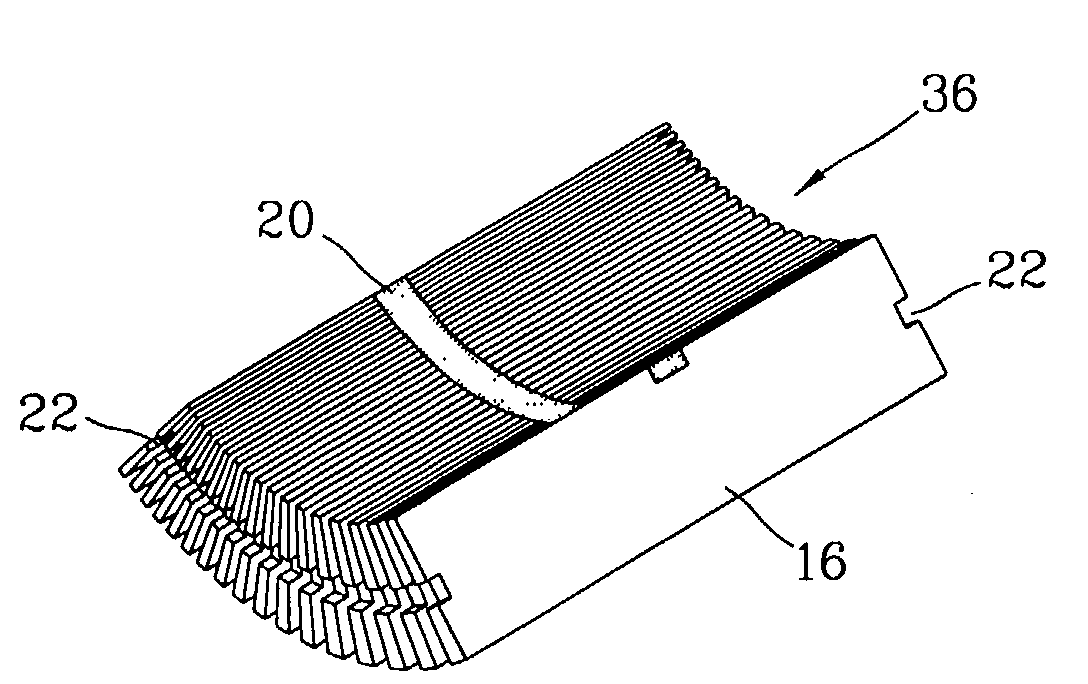
[0038]As shown in FIG. 5, the stator assembly 2 comprises an outer stator 6 formed as a cylinder by laminating a plurality of lamination sheets 10; an inner stator 8 disposed on an inner circumferential surface of...


PUM

PropertyMeasurementUnit
angleaaaaaaaaaa
cylindrical shapeaaaaaaaaaa
lengthsaaaaaaaaaa

Abstract

Disclosed are a stator for a reciprocating motor and a manufacturing method thereof which are able to simplify assembling processes, to reduce assembling time, and thereby to improve productivity by laminating an inner stator to be a straight line shape and bending to be a cylindrical shape. The stator is fabricated by laminating lamination sheets as a straight line and bending it to be a cylindrical shape, and a mounting band is fixed on inner circumferential surface of the lamination sheets so as to maintain the lamination sheets connected when the lamination sheets are bent to be the cylindrical shape.

Description

BACKGROUND OF THE INVENTION[0001]1. Field of the Invention[0002]The present invention relates to a stator for a reciprocating motor and a manufacturing method thereof, and particularly, to a stator for a reciprocating motor and a manufacturing method thereof by which an assembling process can be made in a simple way and assembling time can be reduced.[0003]2. Description of the Background Art[0004]Generally, a reciprocating motor is a motor in which a magnet assembly is linearly reciprocated according to changes of flux formed on a stator. In addition, the reciprocating motor is mainly used in a reciprocating compressor, and a piston of the reciprocating compressor and the magnet assembly are connected to make the piston linearly reciprocate.[0005]FIG. 1 is a cross-sectional view showing a reciprocating motor according to the conventional art, and FIG. 2 is a side view showing the reciprocating motor according to the conventional art.[0006]The conventional reciprocating motor compri...

Claims


Application Information

Patent Timeline
Patent Type & Authority Patents(United States)
IPC IPC(8): H02K33/00H02K1/12H02K15/02F04B17/03H02K1/18F04B17/04H02K33/16
CPCH02K15/02H02K33/16Y10T29/49009H02K1/34F04B17/04
Inventor PARK, KYEONG-BAE
Owner LG ELECTRONICS INC
Why Eureka
Try Eureka