Light emitting element driving device and portable apparatus equipped with light emitting elements

a technology of light emitting elements and driving devices, which is applied in the direction of lighting and heating apparatus, process and machine control, instruments, etc., can solve the problems of limited battery voltage usable range, inability to operate red lights, and inability to fully exploit battery energy, etc., to reduce the energy loss of driving devices, reduce power loss, and extend the usable range of battery voltage

Active Publication Date: 2007-01-02
ROHM CO LTD
View PDF3 Cites 44 Cited by
  • Summary
  • Abstract
  • Description
  • Claims
  • Application Information

AI Technical Summary

Benefits of technology

[0009]It is a still another object of the inventive to reduce the energy loss in the emission of light by different groups of light emitting elements.
[0010]It is a further object of the invention to broaden a limited range of a battery voltage for light emitting elements to a wider usable range.
[0029]The inventive LED driving device is capable of driving different groups of LED having different operating voltages, wherein the group of LED having a low operating voltages (red LED) can be selectively driven by the battery voltage or by a higher voltage stepped up from the battery voltage. When the battery has sufficient power, the group of LED having a low operating voltage are driven directly by the battery voltage to minimize power loss. When the battery power has fallen below a predetermined level, all of the LED groups (red, green and blue LEDs) are automatically driven by the step-up voltage. This helps reduce energy loss by the driving device and extend the usable range of the battery voltage, so that the invention permits effective utilization of energy that remains in a normally non-usable battery.
[0030]In the inventive LED driving device, each group of the LED may be driven by a constant current driver. In this case, the lowest voltages impressed on the constant current drivers is selected by the selection circuit as the detection voltage to automatically regulate the step-up voltage in such a way that the voltages impressed on the constant current drivers are suppressed to minimum allowable levels. Therefore, the power loss by the driving device can be further reduced.

Problems solved by technology

However, such prior art system as disclosed in the literature cited above cannot operate a red LED when the battery voltage has lowered below the operating voltage of the LED.
Thus, the usable range of battery voltage is limited by the operating voltage of a red LED, which presents a problem that for this reason the battery energy cannot be fully exploited.

Method used


Image

  • Light emitting element driving device and portable apparatus equipped with light emitting elements
  • Light emitting element driving device and portable apparatus equipped with light emitting elements
  • Light emitting element driving device and portable apparatus equipped with light emitting elements

Examples


Embodiment Construction

[0036]An inventive light emitting element driving device and portable apparatus equipped with light emitting elements will now be described in detail by way of example with reference to the accompanying drawings.

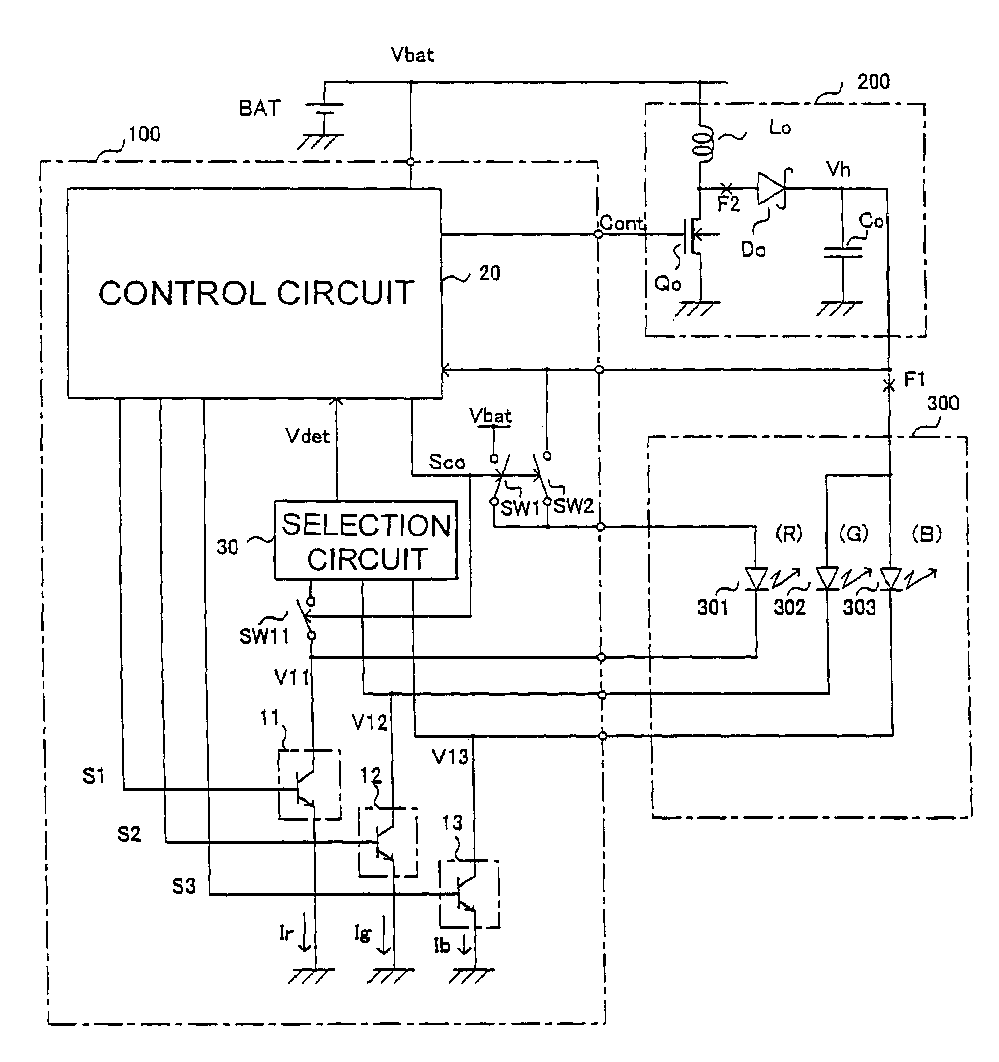
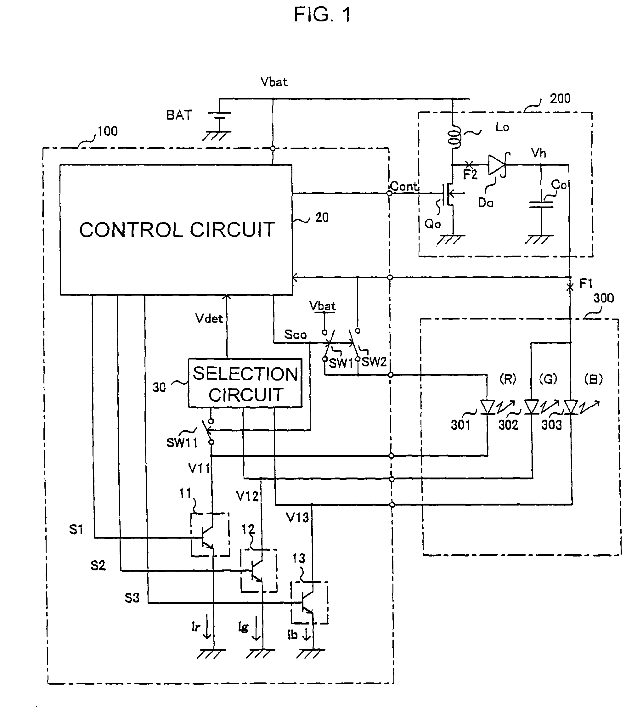
[0037]Referring to FIG. 1, there is shown a light emitting element driving device, comprising a step-up circuit 200 for stepping up the power supply voltage Vbat of a battery BAT (normally having a nominal voltage of 3.6 V) to a required output voltage Vh, and a light emission control IC 100 for controlling the step-up circuit 200. The driving device also has a display 300 equipped with a first group 301 of light emitting elements, a second group 302 of light emitting elements, and a third group 303 of light emitting elements acting as loads connected to the step-up circuit 200. In the example shown herein, the first group 301, second group 302, and third group 303 of light emitting elements are red (R), green (G), and blue (B) LEDs, respectively. LED groups 301–303 may serv...


PUM


Abstract

A driving device for driving multiple (R-, G-, and B-) groups of LEDs operative at different voltages, utilizing a battery supplying a power supply voltage of a step-up voltage. Under normal operating conditions, R-LEDs are driven by the battery voltage, but G- and B-LEDs are driven by the step-up voltage. The battery voltage is monitored to ensure that all the LEDs are driven by the step-up voltage when the battery voltage has lowered below a predetermined level, thereby reducing the power loss by the LEDs while emitting light and extending the permissible range of the battery voltage.

Description

FIELD OF THE INVENTION[0001]This invention relates to a device for driving light emitting elements such as light emitting diodes (LEDs) operable at high voltage (the device hereinafter referred to as light emitting element driving device or simply driving device), and to a portable apparatus equipped with such light emitting elements.BACKGROUND OF THE INVENTION[0002]Light emitting elements such as LEDs are used as, for example, multicolor display elements of a cellular phone for displaying data received, back light sources of an LCD (liquid crystal display), or flash light sources of a camera. For these purposes, red (R), green (G), and blue (B) LEDs are often used simultaneously.[0003]To activate an LED for emission of light, a driving voltage is required that amounts to a voltage drop across the LED for emission of a required amount of light plus a control voltage for controlling the driver that controls the luminance of the LED. In a case where LEDs of a portable apparatus for ex...

Claims


Application Information

Patent Timeline
Patent Type & Authority Patents(United States)
IPC IPC(8): H05B37/00H01L27/14F21L4/02G09G3/20G09G3/36H01L33/00H04B10/40H04B10/50H04B10/60
CPCG09G3/3413H05B33/0815H05B33/0827Y10S362/806Y10S362/80Y10S362/802H05B45/46Y02B20/30H05B45/38B62K1/00
Inventor KOMIYA, KUNIHIROKITAGAWA, ATSUSHI
Owner ROHM CO LTD
Why Eureka
Try Eureka