Spectroscopic ellipsometer and polarimeter systems

a technology of ellipsometer and polarimeter, which is applied in the direction of spectrometry/spectrophotometry/monochromator, instruments, optical radiation measurement, etc., can solve the problems of increased heat production and accompanying production of ozone levels to which personnel cannot be safely exposed, unacceptably distributed produced ozone into surrounding atmosphere, and rotating compensator ellipsometer systems do not demonstrate “dead spots”

Inactive Publication Date: 2007-01-02
J A WOOLLAM CO
View PDF55 Cites 29 Cited by
  • Summary
  • Abstract
  • Description
  • Claims
  • Application Information

AI Technical Summary

Benefits of technology

[0211]It is another purpose and/or objective of the disclosed invention to describe a method of quickly obtaining data corresponding to a m...

Problems solved by technology

A problem inherrant in operation, however, is that to increase intensity output therefrom or extend the useable wavelength range lower limit to say 220 nm or even 193 nm and below, results in increased heat production and accompanying production of levels of ozone to which personnel can not be safely exposed.
The temperature of the source can be controled by flowing a gas therearound to dissipate increased heat, but this also serves to unacceptably distribute produced ozone into surrounding atmosphere when it is produced.
It is noted that Rotating Compensator Ellipsometer Systems do not demonstrate “Dead-Spots” where obtaining data is difficult.
They can read PSI and DELTA of a Material System over a full Range of Degrees with the only limitation being that if PSI becomes essentially zero (0.0), o...

Method used


Image

  • Spectroscopic ellipsometer and polarimeter systems
  • Spectroscopic ellipsometer and polarimeter systems
  • Spectroscopic ellipsometer and polarimeter systems

Examples


Embodiment Construction

Invention System

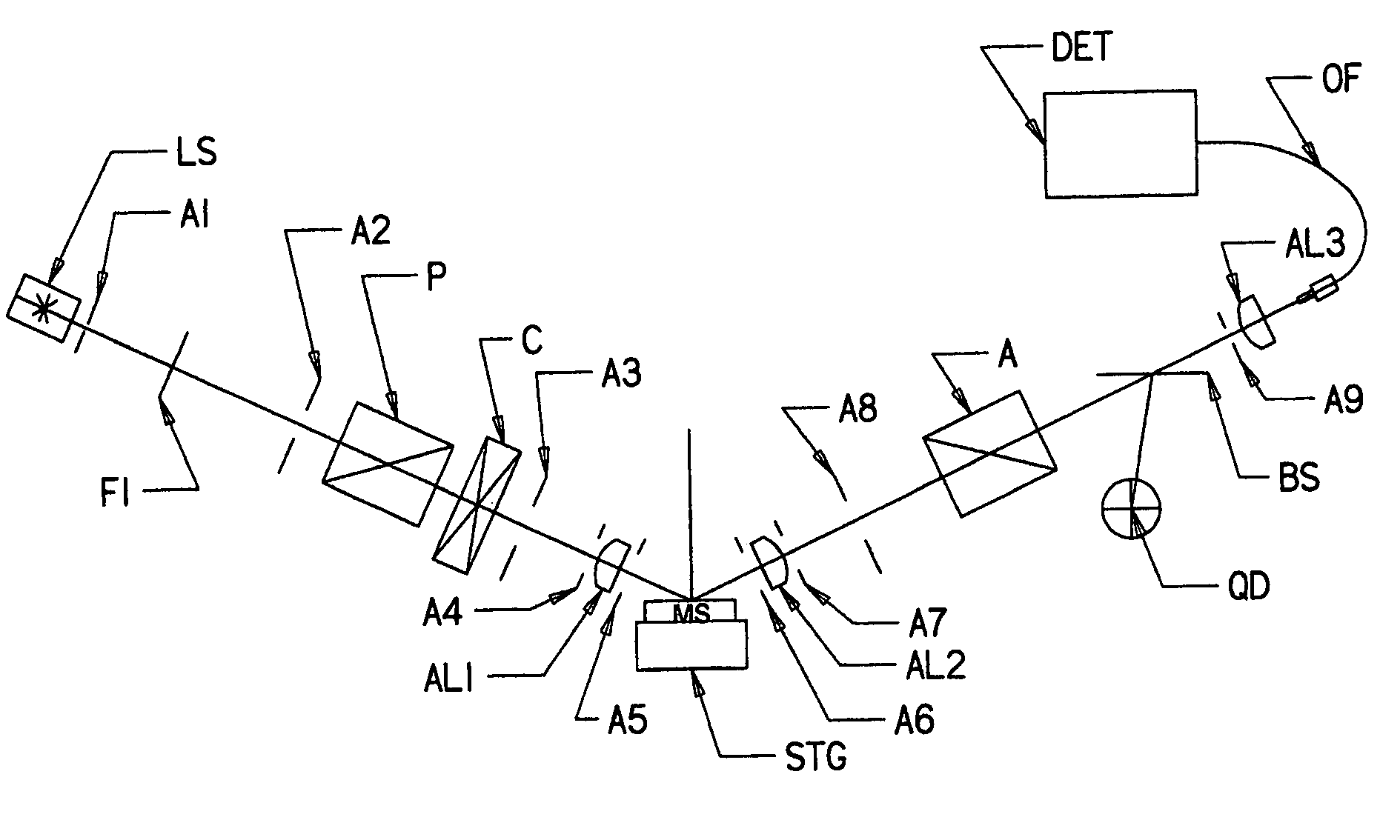
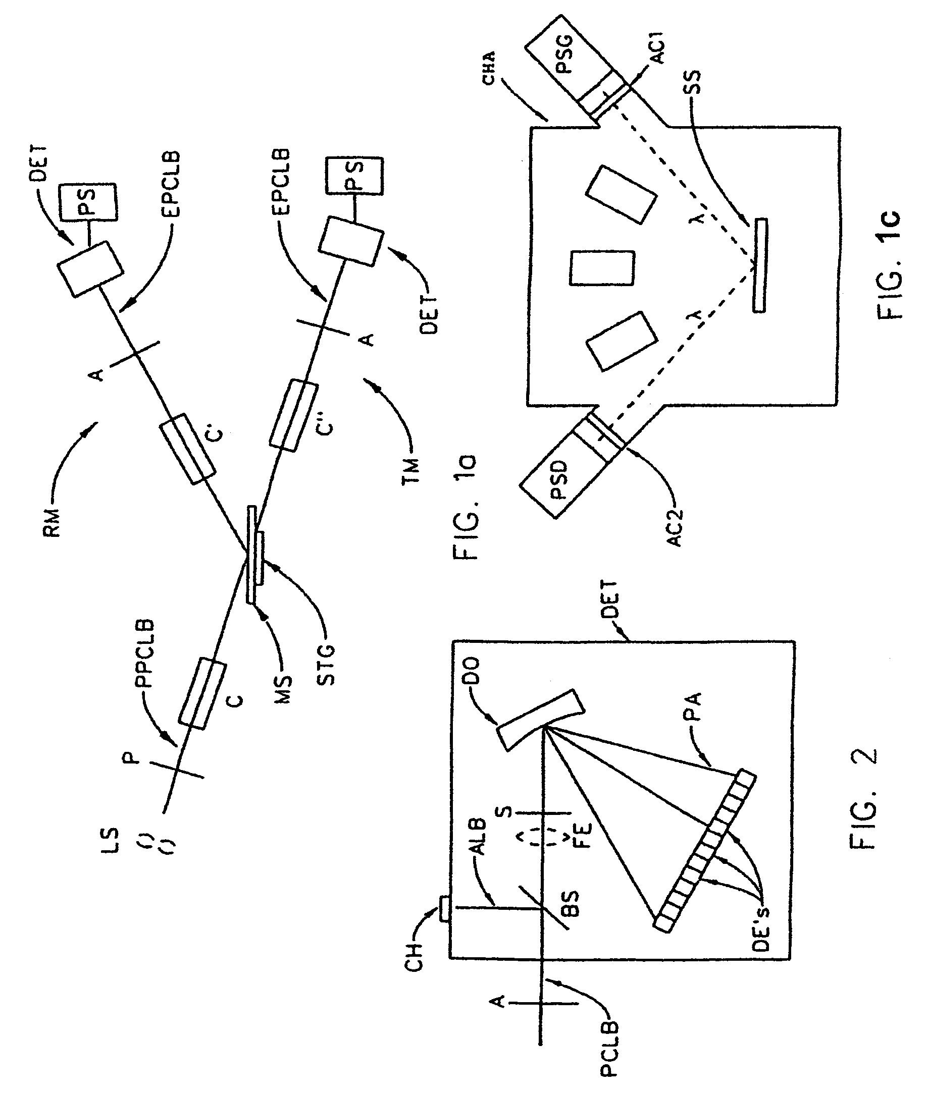
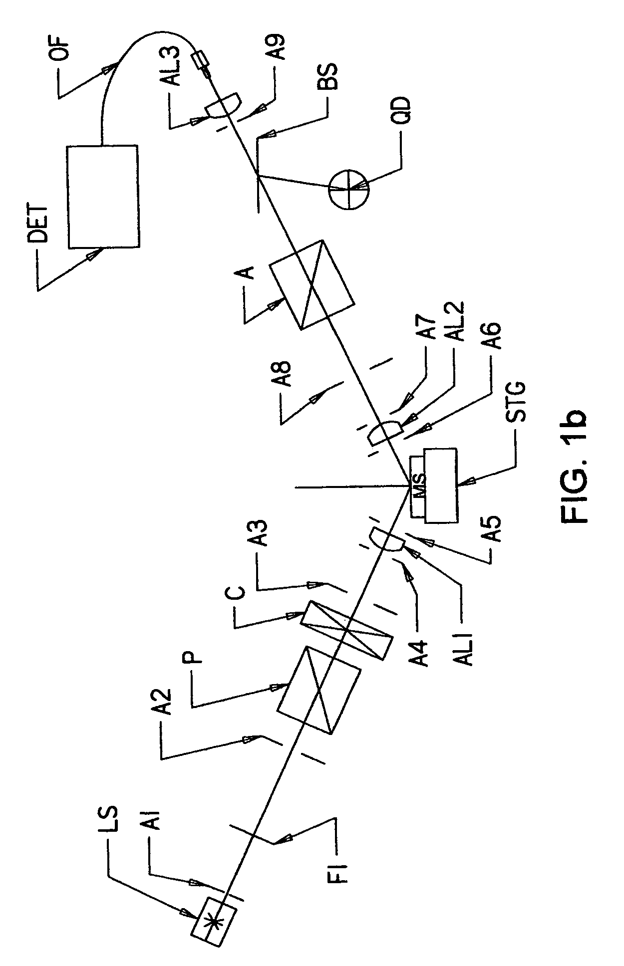
[0256]Referring now to FIG. 1a, there is demonstrated a Material System Investigation System, (ie. a Spectroscopic Ellipsometer System), with provision to investigate a Material System (MS) in either a Reflection Mode (RM) or a Transmission Mode (TM). It is to be noted that said Material System investigation System is generally comprised of a Source of a Polychromatic Beam of Electromagnetic Radiation (LS), (ie. a Broadband electromagnetic radiation source), a Polarizer Means (P), a Material System, supporting Stage (STG), an Analyzer Means (A) and a Detector Elements (DE's) containing Photo Array Detector Means System (DET). Also note, however, that FIG. 1a shows Reflection Mode System Compensator(s) Means (C) and (C′) and Transmission Mode System Compensator(s) Means (C) and (C″) as present. It is to be understood that a Compensator Means can be placed ahead of, and / or after a Material System (MS) supporting Stage (STG) in either a Reflection Mode or Transmission M...


PUM


Abstract

A spectroscopic ellipsometer or polarimeter system having a source of a polychromatic beam of electromagnetic radiation, a polarizer, a stage for supporting a material system, an analyzer, a dispersive optics and a detector system which comprises a multiplicity of detector elements, there being apertures before the stage for supporting a material system, and thereafter, the system being present in an environmental control chamber.

Description

[0001]This Application is a CIP of application Ser. No. 10 / 034,800 Filed Dec. 28, 2001 now U.S. Pat. No. 6,822,738 and therevia a CIP of Ser. No. 09 / 945,962 filed Sep. 4, 2001 now U.S. Pat. No. 7,075,649 and Ser. No. 09 / 496,011 filed Feb. 1, 2000 (U.S. Pat. No. 6,353,477), which is a CIP of Ser. No. 09 / 246,888 filed Feb. 8, 1999 (U.S. Pat. No. 6,084,675), which is a CIP of Ser. No. 08 / 912,211 filed Aug. 15, 1997 (U.S. Pat. No. 5,872,630), which is a CIP Ser. No. 08 / 530,892 filed Sep. 20, 1995 (U.S. Pat. No. 5,666,201) and therevia is a CIP of Ser. No. 08 / 618,820 filed Mar. 20, 1996 (U.S. Pat. No. 5,706,212).[0002]This Application also Claims Benefit of Provisional Application Ser. No. 60 / 473,615 Filed May 28, 2003; 60 / 437,023 Filed Dec. 31, 2002, 60 / 424,589, Filed Nov. 7, 2002; and 60 / 427,043 Filed Nov. 18, 2002.TECHNICAL FIELD[0003]The disclosed invention relates to spectroscopic ellipsometer and polarimeter systems, and more particularly to a specific configuration comprising a so...

Claims


Application Information

Patent Timeline
IPC IPC(8): G01J4/00
CPCG01J3/02G01J3/0218G01J3/0224G01J3/0229G01J3/024G01J3/10G01J3/447G01J4/00G01N21/211G01N21/274G01J3/0286G01N2021/213
Inventor WOOLLAM, JOHN A.JOHS, BLAINE D.HERZINGER, CRAIG M.HE, PINGLIPHARDT, MARTIN M.PFEIFFER, GALEN L.
Owner J A WOOLLAM CO
Why Eureka
Try Eureka